Floor Structure for a Fuselage
a technology of floor structure and fuselage, which is applied in the direction of fuselage, sustainable transportation, transportation and packaging, etc., can solve the problems of increasing the difficulty of accessing this edge region, increasing the cost of supply lines, etc., and increasing the cost of production
- Summary
- Abstract
- Description
- Claims
- Application Information
AI Technical Summary
Benefits of technology
Problems solved by technology
Method used
Image
Examples
first embodiment
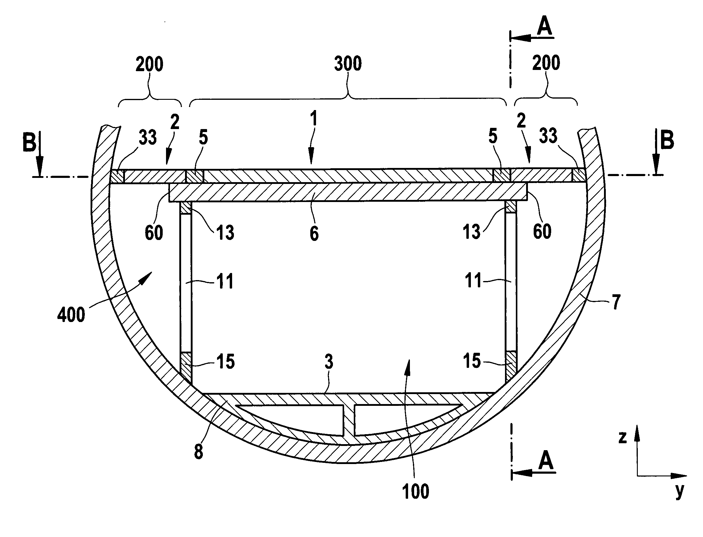
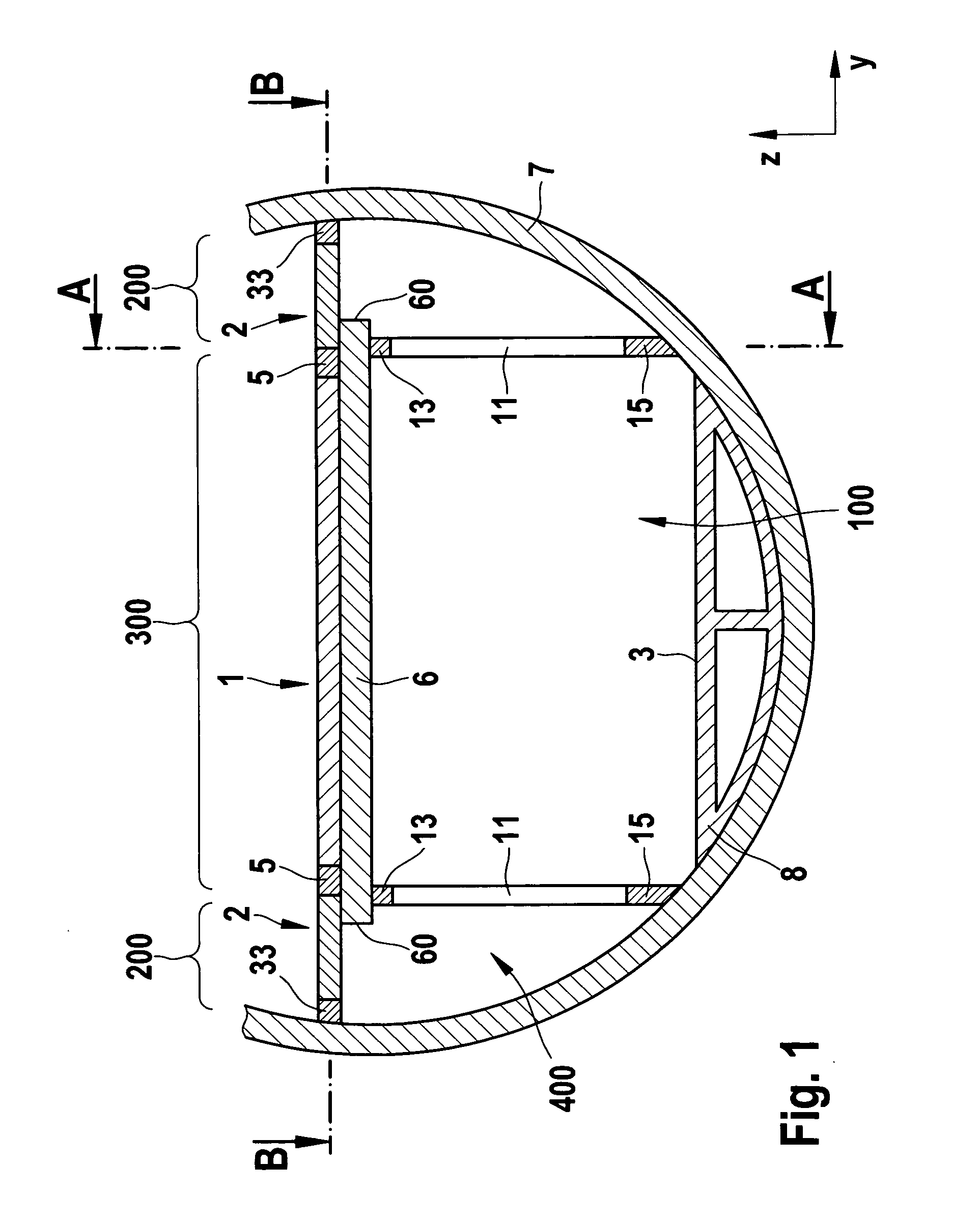
[0050]In FIG. 4, a detailed view is shown for a further embodiment of the outer portion 200 and the outer floor plate 2. The elements described in connection with the first embodiment may be adopted in this embodiment. The outer plate 2 may substantially consist of a plate 35, which is produced from a composite material. In one alternative, an intermediate layer with a honeycomb structure is inserted in the composite material. In order to fasten the outer plate to the cross beam 6 and / or the frame 7, continuous sleeves 32 are inserted in the outer plate 2. By means of these sleeves 32, suitable fastening materials, for example rivets, screws, bolts etc. may be passed through. The sleeves 32 protect the body 35 made of the composite material from damage, when the fastening means are inserted or removed. Corresponding acting forces or stresses are absorbed by the sleeves 32. As a result, it is possible to fasten and to remove repeatedly the outer floor plates 2. Such a removal is, for...
second embodiment
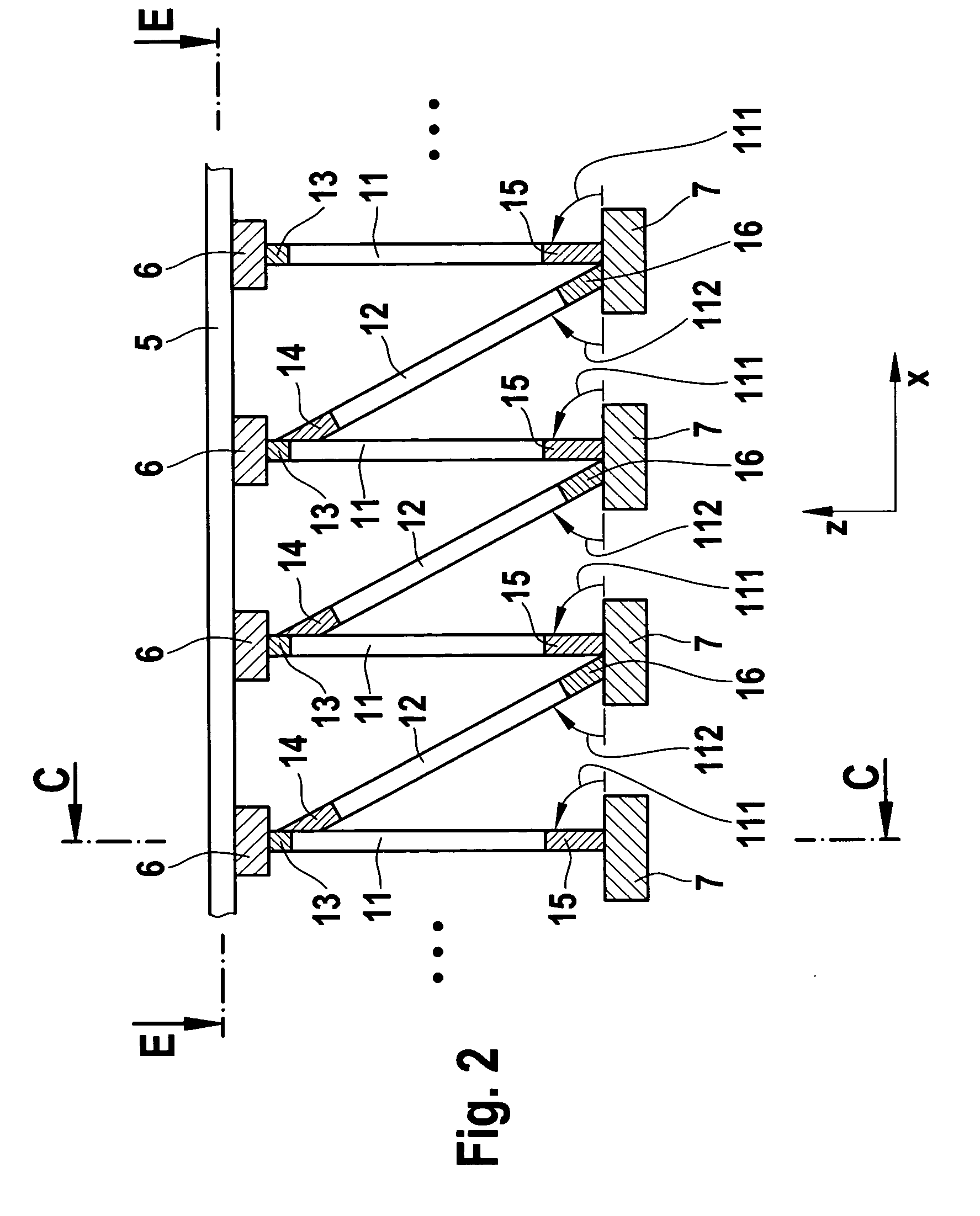
[0055]In FIG. 5, a side view of the present invention is shown the front view and the plan view of which correspond to FIGS. 1 and 2, respectively. Instead of a perpendicular strut and an oblique strut, two oblique struts 21, 22 are used in this embodiment. One strut 21 of the struts 21, 22 has a forwardly inclined direction 121 or a corresponding direction vector 121, and the other strut 22 has a rearwardly inclined direction 122 or corresponding direction vector 122. The term “forwardly inclined” is understood to denote, when viewing the strut from bottom to top, that the strut points towards the aircraft tip (negative longitudinal direction x). The term “rearwardly inclined” accordingly denotes that the strut 22, when viewed from bottom to top, points towards the aircraft tail (i.e. in the positive longitudinal direction x). By this arrangement of the forwardly inclined and rearwardly inclined struts 21, 22, a flux of force is also obtained of a force acting in the longitudinal d...
fourth embodiment
[0058]In FIGS. 11 and 12, the present invention is shown which serves to describe an example for fastening the struts to the frames 7. The individual frames 7 of an aircraft fuselage are arranged parallel to one another and connected via spars 51 extending in the longitudinal direction x. A fastening device 53 may be arranged on such a spar. Said fastening device has suitable fastening tabs, bores 54 or projections to which the strut ends of the struts 73, 74 may be fastened. The strut ends may, for example, be provided in the form of joints, preferably hinged joints. For mechanical stability and improved force transmission, it may be advantageous to reinforce the spar 51 on which the mounting device 53 is arranged, by means of a reinforcing device 52, in order to ensure an improved force transmission.
[0059]The cross beam used in the aforementioned embodiments, advantageously already has a low weight due to its minimal length. An additional weight reduction may be achieved by the us...
PUM
 Abstract
Description
Claims
Application Information
 - R&D
- Intellectual Property
- Life Sciences
- Materials
- Tech Scout
- Unparalleled Data Quality
- Higher Quality Content
- 60% Fewer Hallucinations
Browse by: Latest US Patents, China's latest patents, Technical Efficacy Thesaurus, Application Domain, Technology Topic, Popular Technical Reports.
© 2025 PatSnap. All rights reserved.Legal|Privacy policy|Modern Slavery Act Transparency Statement|Sitemap|About US| Contact US: help@patsnap.com


