
Antenna using electrically conductive ink and production method thereof

Inactive Publication Date: 2010-02-25
EMW CO LTD
View PDF8 Cites 2 Cited by
  • Summary
  • Abstract
  • Description
  • Claims
  • Application Information

AI Technical Summary

Benefits of technology

[0033]According to the present invention, since the loss of current in an antenna can be prevented, an antenna with a good gain can be fabricated using electrically conductive ink through a simple process.
[0034]Furthermore, according to the present invention, since an amount of expensive electrically conductive ink used can be minimized without affecting the performance of the antenna, the antenna can be fabricated at low cost.

Problems solved by technology

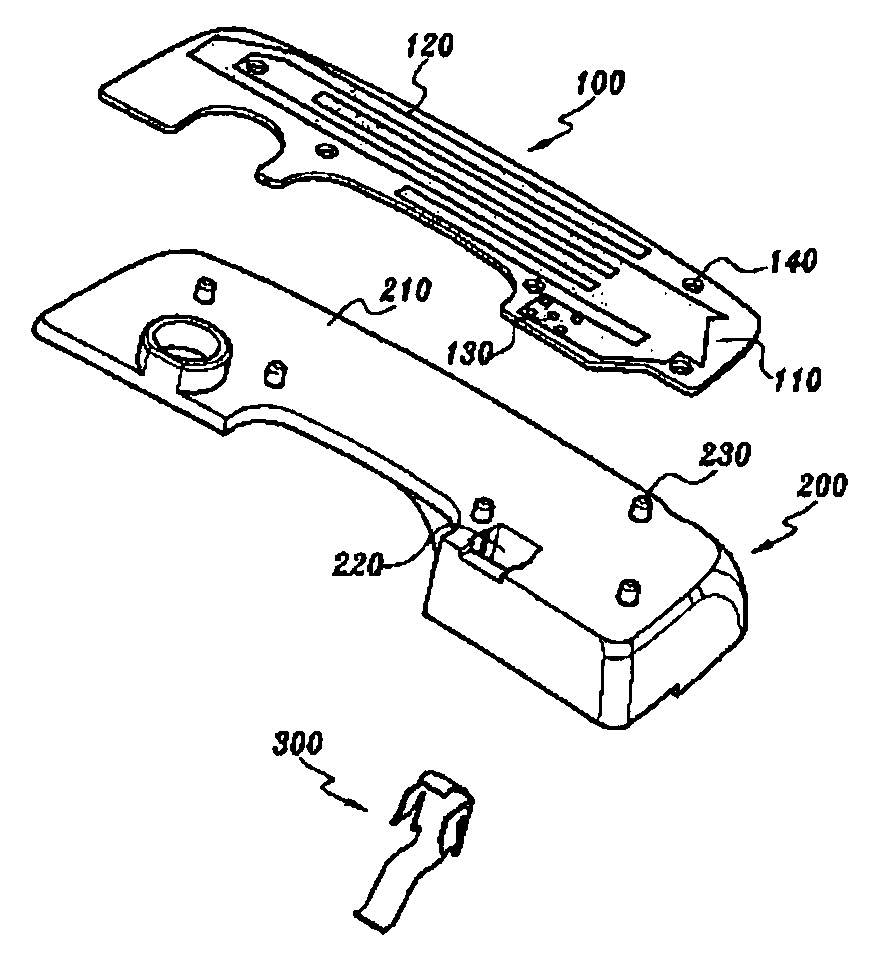
However, it is inconvenient and expensive to form the radiator 120 using the deposition process.
If the antenna radiator is formed of the electrically conductive ink, however, there is a problem in that the gain of the antenna is low.
Furthermore, since the electrically conductive ink is very expensive, the production cost of the antenna rises.

Method used


Image

  • Antenna using electrically conductive ink and production method thereof
  • Antenna using electrically conductive ink and production method thereof
  • Antenna using electrically conductive ink and production method thereof

Examples


first embodiment

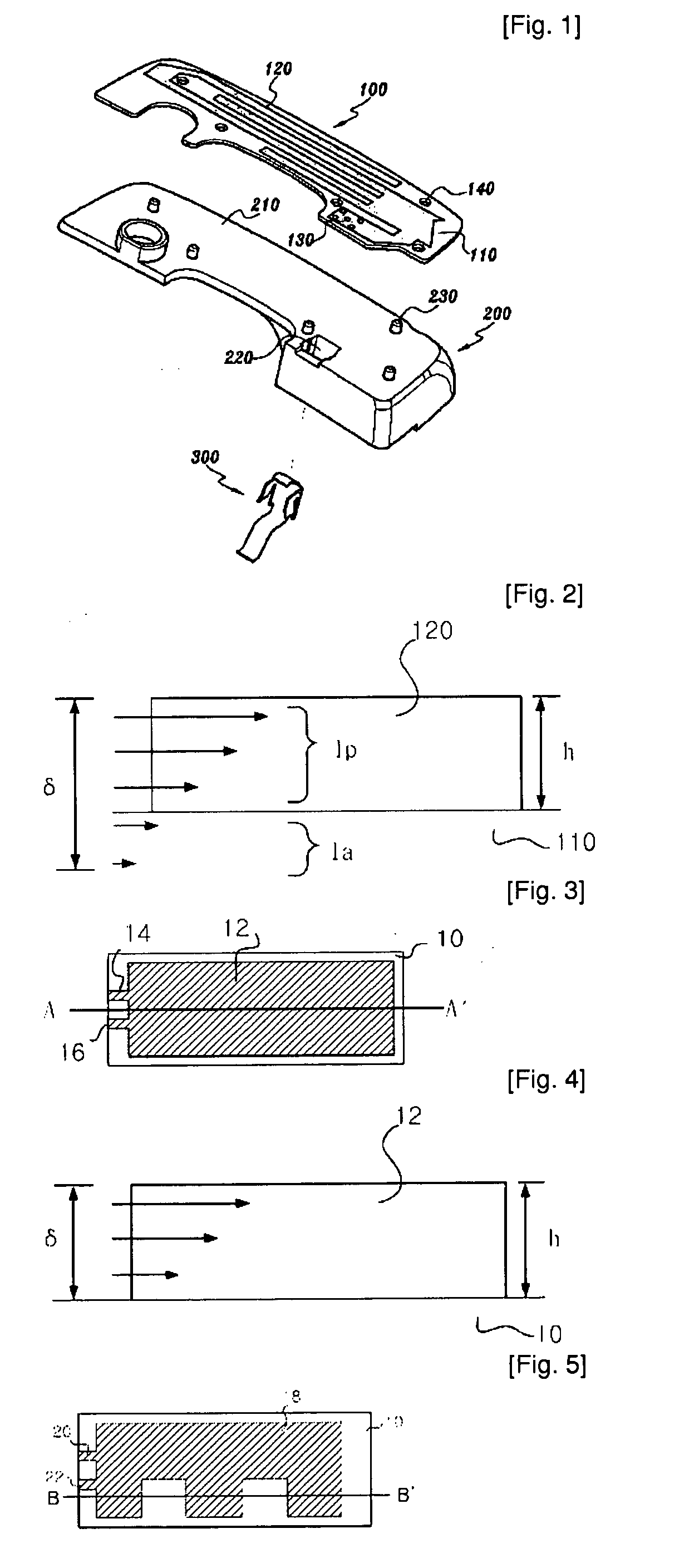
[0049]FIG. 3 is a top view of a single band antenna according to the present invention, and FIG. 4 is a cross-sectional view of the antenna taken along line A-A′ in FIG. 3. Referring to FIG. 3, the antenna of the present embodiment includes an antenna radiator 12 formed of electrically conductive ink on the substrate 10 through printing, and a ground unit 14 and a feeding unit 16 formed in the antenna radiator 12. The electrically conductive ink used to form the antenna radiator 12 may be known one, but preferably a mixture of 65 to 70% by weight of silver (Ag) and 30 to 35% by weight of an additive. The additive may be a mixture of resin, a drying agent, and a dispersing agent. The resin serves to prevent a direct contact between silver (Ag) and oxygen in order to prevent corrosion. The drying agent serves to accelerate the dry of ink, reducing the manufacturing time of an antenna. The dispersing agent serves to increase the dispersibility of silver particles.

[0050]Meanwhile, in or...

second embodiment

[0052]FIG. 5 is a top view of a dual band antenna according to the present invention, and FIG. 6 is a cross-sectional view of the antenna taken along line B-B′ in FIG. 5. The antenna of the present embodiment includes an antenna radiator 18 formed by printing electrically conductive ink on a substrate 10. A ground unit 20 and a feeding unit 22 are also formed in the antenna radiator 18. The antenna radiator 18 can be formed by printing the same electrically conductive ink as that of the previous embodiment. Meanwhile, the antenna radiator 18 of the present embodiment is printed in an E shape, as shown in FIG. 5, and accordingly has a dual band characteristic. However, those having skilled in the art will easily understand that the shape of the radiator 18 is not limited to the E shape, but may have a variety of shapes, such as a meander type, a rectangular type, a triangular shape, and a circular shape, depending on a frequency band of an antenna and a multi-band characteristic.

[005...

third embodiment

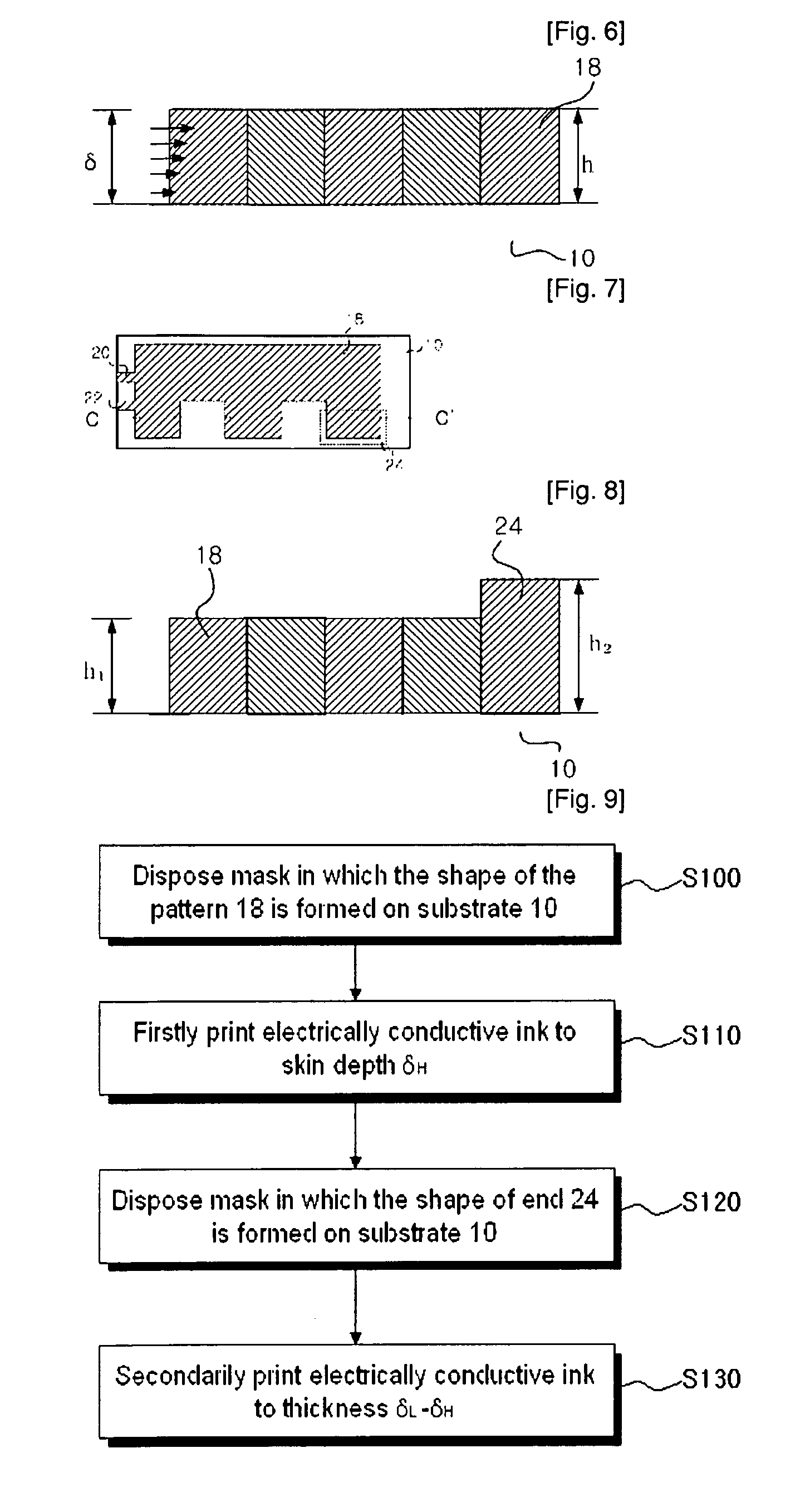
[0058]FIG. 7 is a top view of a dual band antenna according to the present invention, and FIG. 8 is a cross-sectional view of the antenna taken along line C-C′ in FIG. 7. The antenna of the present embodiment includes an antenna radiator 18 formed by printing electrically conductive ink on a substrate 10. A ground unit 20 and a feeding unit 22 are also formed in the antenna radiator 18. The antenna radiator 18 can be formed by printing the same electrically conductive ink as that of the previous embodiment. The antenna radiator 18 of the present embodiment is printed in an E shape, and accordingly has a dual band characteristic. However, those having skilled in the art will easily understand that the shape of the radiator 18 is not limited to the E shape, but may have a variety of shapes, such as a meander type, a rectangular type, a triangular shape, and a circular shape, depending on a frequency band of an antenna and a multi-band characteristic.

[0059]In general, the dual band ant...


PUM


Abstract

Disclosed is an antenna having an antenna radiator formed by printing electrically conductive ink on a substrate. An antenna radiator according to an embodiment of the present invention is formed to the same thickness as a skin depth with respect to an operation frequency of the antenna. Therefore, an antenna can be fabricated using a small amount of electrically conductive ink while not reducing the gain of the antenna. Further, an antenna radiator according to another embodiment of the present invention is formed to the same thickness as a skin depth with respect to a predetermined frequency at a corresponding hot spot with respect to the frequency. Accordingly, an amount of electrically conductive ink used can be further reduced while maintaining the gain of the antenna.

Description

TECHNICAL FIELD[0001]The present invention relates, in general, to an antenna for wireless communication, and more particularly, to an antenna for wireless communication, in which an antenna radiator is formed of electrically conductive ink and the thickness of the radiator is determined according to a use frequency of an antenna.BACKGROUND ART[0002]In general, an antenna for wireless communication includes a feeding unit and a ground unit. The antenna further includes an antenna radiator connected to a RF circuit within a terminal device through the feeding unit and the ground unit, and a base supporting the antenna radiator.[0003]The antenna radiator is formed of an electrically conductive material and has a pre-determined electrical length. Accordingly, the antenna radiator resonates at a target frequency to radiate and / or receive electromagnetic wave, and thus serves as a radiator. The antenna radiator may have a variety of shapes, such as a meander type, a helical type, a recta...

Claims


Application Information

Patent Timeline
IPC IPC(8): H01Q1/38B05D5/12H01Q5/10
CPCH01Q9/0421H01Q1/243
Inventor RYOU, BYUNG-HOONSUNG, WON-MOPARK, SANG-HOON
Owner EMW CO LTD
Learn More