Packet recovery method, communication system, information processing device, and program

a recovery method and information processing technology, applied in error prevention, digital transmission, data switching networks, etc., can solve the problems of reduced efficiency of utilizing frequency bands in communications from reception nodes, increased message size, and increased susceptibility to packet loss and fragmentation, so as to reduce the amount of data in an acknowledgement message, prevent redundant retransmission, and reduce the efficiency of utilizing frequency bands

Active Publication Date: 2010-02-25
NEC CORP
View PDF6 Cites 22 Cited by
  • Summary
  • Abstract
  • Description
  • Claims
  • Application Information

AI Technical Summary

Benefits of technology

[0035]According to the present invention, it is possible to reduce the amount of data in an acknowledgement message and reduce a lower efficiency of utilizing a frequency band. Also, when first transmission packets and retransmission packets are transmitted in parallel using a plurality of paths, it is possible to prevent redundant retransmissions caused by inter-path jitter.

Problems solved by technology

The Sack-based transmission shown in FIG. 1 has a problem in which there is a lower efficiency of utilizing a frequency band in communications from reception node 102 to transmission node 101 because the acknowledge message increases in size as the number of Sack blocks increases.
Also, when the acknowledge message is contained in the header of a data packet as in TCP, an increase in the number of Sack blocks causes a problem in which there is a higher susceptibility to packet loss and fragmentation.
The influence of these problems can be alleviated by limiting the number of Sack blocks, but in this event, if a large number of packets are lost, all loss information cannot be contained in the acknowledgement message.
As a result, a problem arises in which there is a delay in detecting packets which must be retransmitted, and an increase in packet retransmission delay.

Method used


Image

  • Packet recovery method, communication system, information processing device, and program
  • Packet recovery method, communication system, information processing device, and program
  • Packet recovery method, communication system, information processing device, and program

Examples


first embodiment

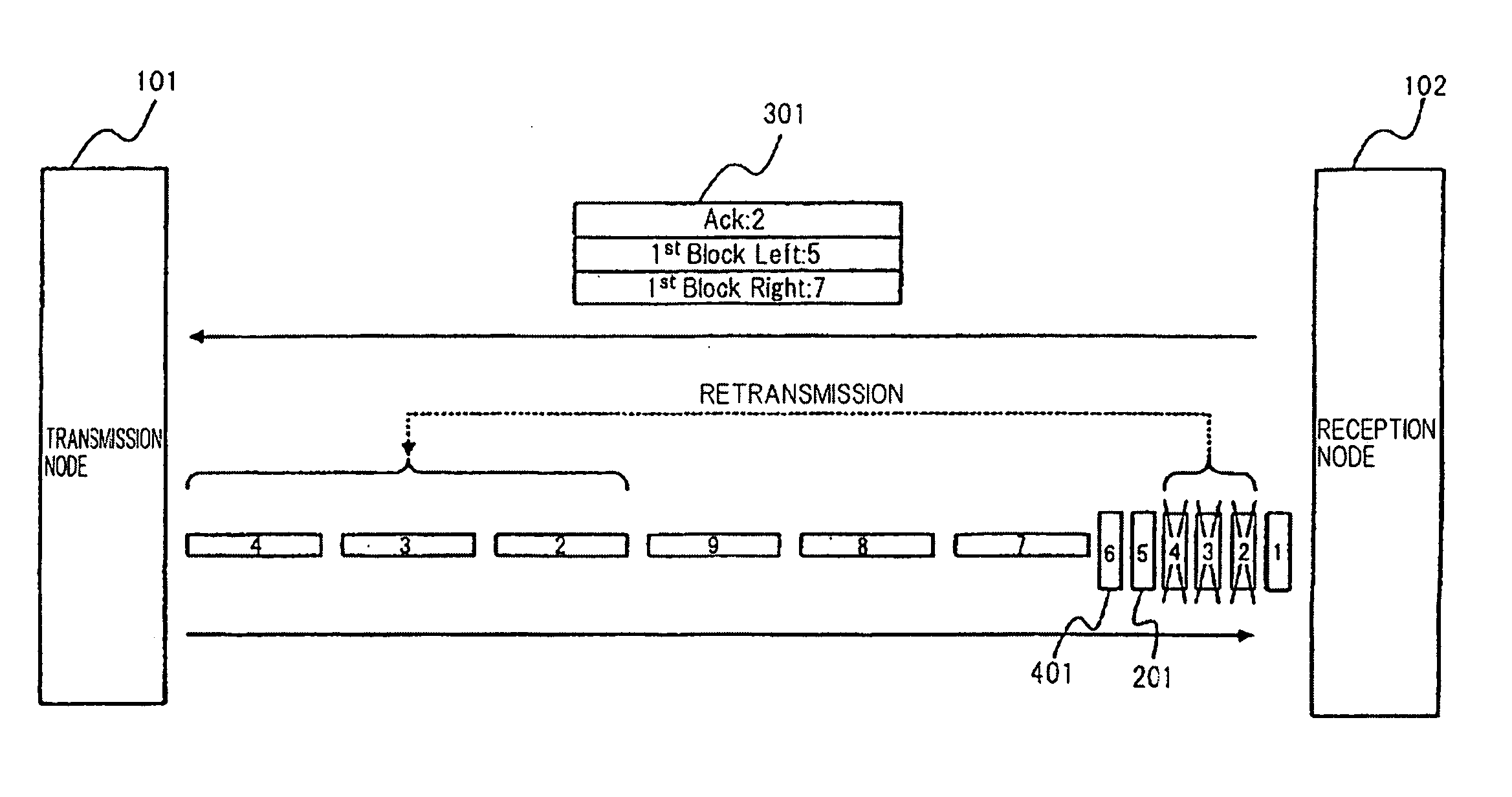
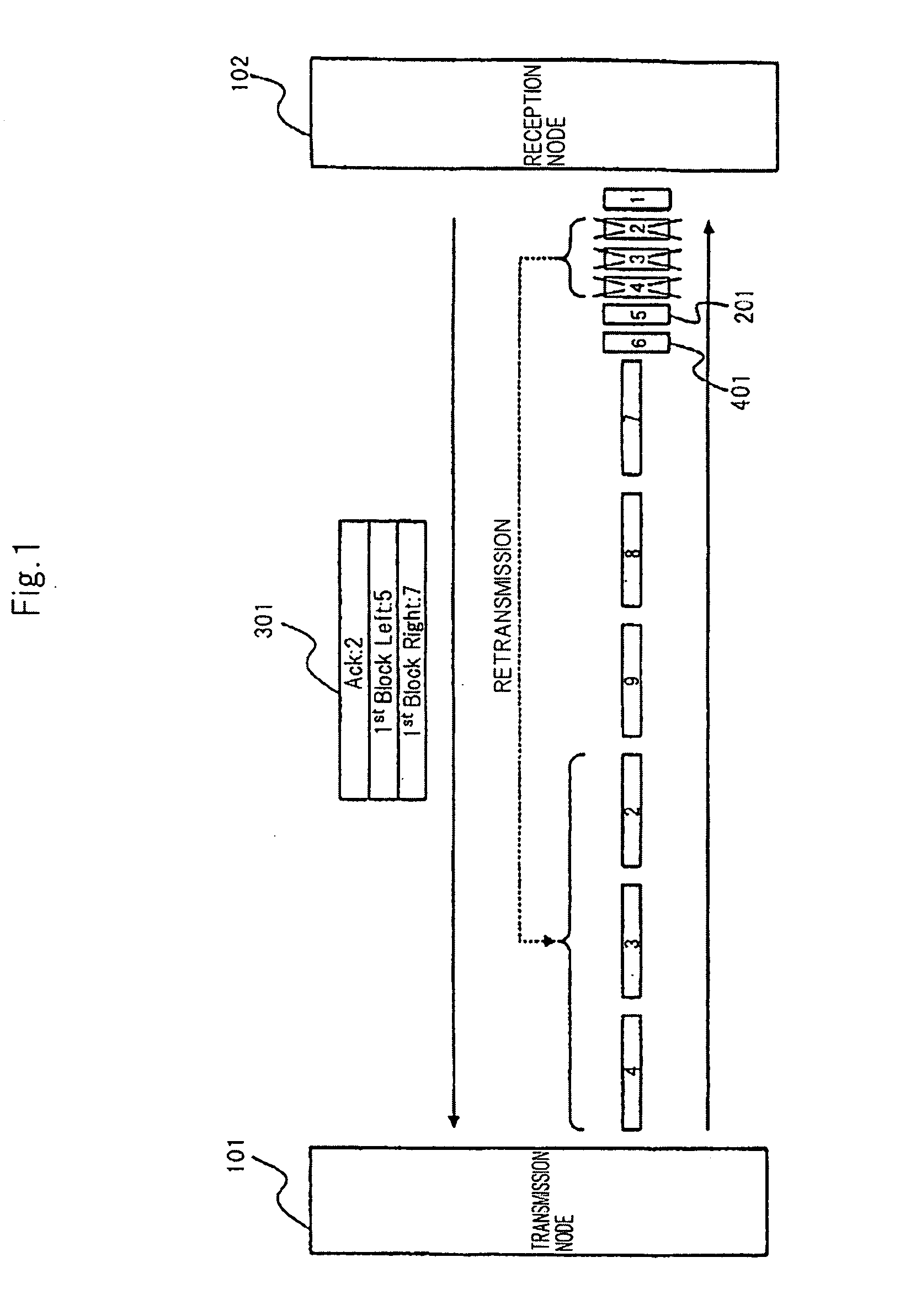
[0055]A description will be given of the configuration of a communication system of this embodiment. FIG. 3 is a block diagram showing an exemplary configuration of the communication system in this embodiment.

[0056]Transmission node 111 and reception node 112 shown in FIG. 3 are information processing devices such as computers, PDAs (Personal Digital Assistants), routers, server devices, or the like which are connected through network 50 such as the Internet. In this regard, a router may be provided in network 50 for forwarding packets. Transmission node 111 is comparable to a first node of the present invention, while reception node 112 is comparable to a second node of the present invention.

[0057]When packets are transmitted / received between two nodes through network 50, which are not limited to a case where packets are transmitted from one to the other, and there is a reverse case as well, a packet transmission side is herein designated as transmission node 111, and a reception s...

second embodiment

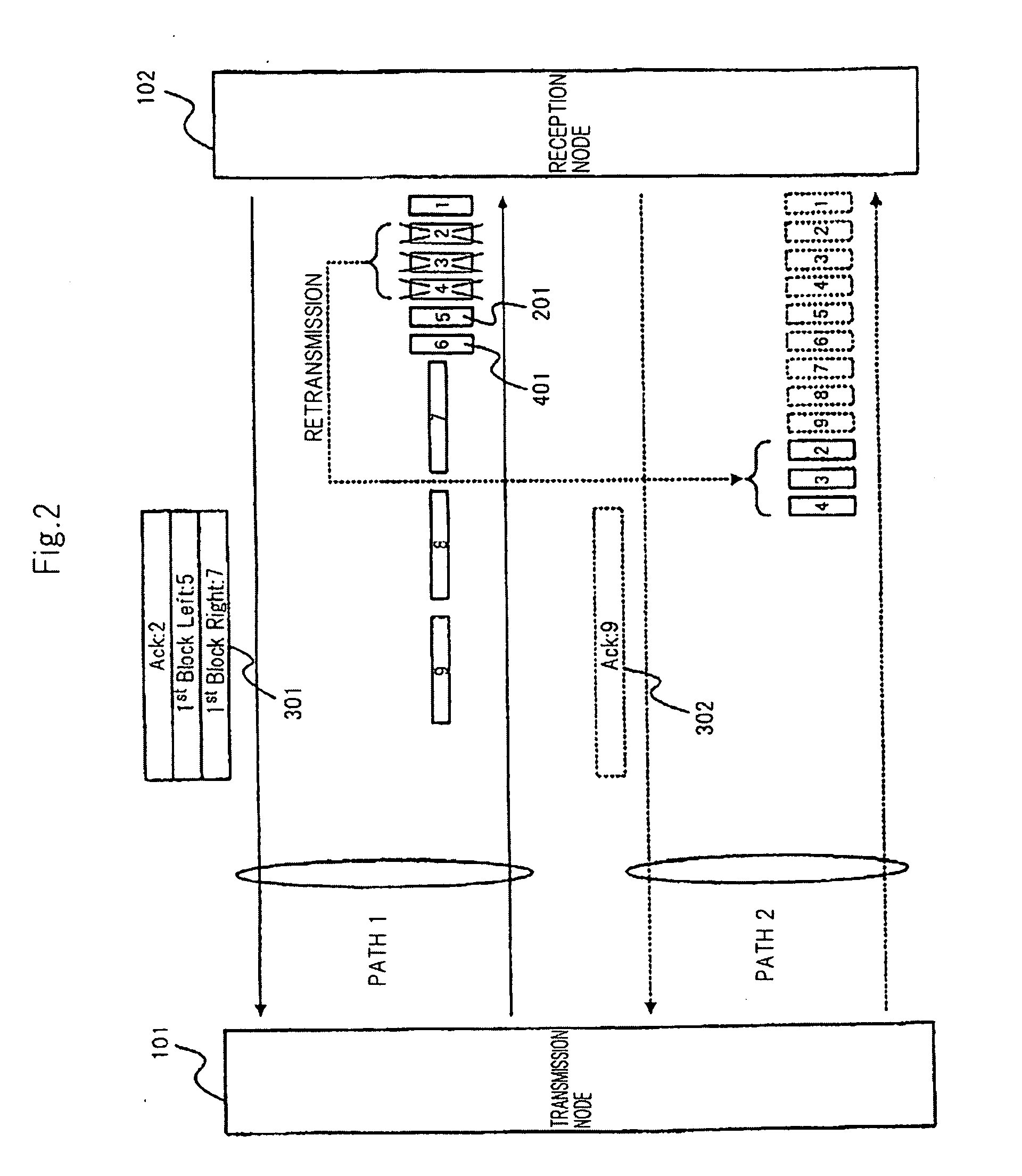
[0073]The first embodiment relates to packet retransmission processing when there is a single communication path between two nodes, whereas this embodiment relates to packet retransmission processing when a plurality of communication paths are available between two nodes.

[0074]A description will be given of the configuration of a communication system of this embodiment. Since an information processing device of this embodiment is similar to that of the first embodiment, aspects different from the first embodiment will be described in detail with reference to FIG. 3.

[0075]In this embodiment, assume that there are a plurality of paths within network 50, that are communication paths between transmission node 111 and reception node 112. In the following, for simplifying the description, there are two selectable paths, path 1 and path 2.

[0076]In this embodiment, control unit 117 of transmission node 111 generates a retransmission packet which is given a new sequence number, and inserts A...


PUM


Abstract

A packet recovery method of the present invention is a packet recovery method upon loss of a plurality of packets transmitted from a first node 111 to second node 112 through a network in the order of sequence numbers assigned to each of said packets, wherein second node 112, upon detection of a loss of a packet transmitted from first node 111, transmits an acknowledgement message, including a sequence number of a packet whose receipt has been confirmed or whose loss has been detected and including information on the lost packet, to first node 111 through the network. Then, first node 111, upon receipt of the acknowledgement message from second node 112, assigns a sequence number that is different from that of any of the plurality of packets to a retransmission packet which is a packet to be retransmitted, and subsequently, transmits an acknowledgement-to-acknowledgement message attached to the retransmission packet through the network for notifying that the acknowledgement message has been received to second node 112.

Description

TECHNICAL FIELD[0001]The present invention relates to a packet recovery method, a communication system, an information processing device, and a program for causing a computer to execute the method.BACKGROUND ART[0002]When two nodes communicate packets through a network such as the Internet, some packets may be lost. Techniques concerning packet retransmission methods have been proposed as methods of addressing packet loss. JP-9-46375A (hereinafter referred to as “Document 1”) discloses an example thereof.[0003]In a technique disclosed in Document 1, the flow and order of transmission packets are controlled between a transmission node and a reception node where, when a queue is caused by packet loss on the reception node, or when the reception node fails to receive packets associated with the queue in a certain time period, the transmission node is notified of a request for retransmitting the packets associated with the queue.[0004]Also, when a plurality of flows exist between two no...

Claims


Application Information

Patent Timeline
Patent Type & Authority Applications(United States)
IPC IPC(8): H04L12/56
CPCH04L1/1867H04L1/1809H04L2001/0096H04L1/1896
Inventor NAKATA, TSUNEO
Owner NEC CORP
Why Eureka
Try Eureka