Plasma Enhanced Rotor

a technology of enhanced rotors and rotors, which is applied in the direction of rotors, engine starters, liquid fuel engines, etc., can solve the problems of limiting the operability of these engines, requiring a high level of stability margin throughout the flight envelope, and causing common instabilities such as stalls, so as to reduce the instabilities of compression systems and increase the stable operating range of compression systems

Inactive Publication Date: 2010-02-25
GENERAL ELECTRIC CO
View PDF33 Cites 25 Cited by
  • Summary
  • Abstract
  • Description
  • Claims
  • Application Information

AI Technical Summary

Benefits of technology

[0009]In another exemplary embodiment, a mitigation system is provided to mitigate compression system instabilities for increasing the stable operating range of a compression system, the system comprising at least one plasma generator located on a r

Problems solved by technology

Some of these engines may also have a fixed area exhaust nozzle, which limits the operability of these engines.
The conflicting requirements of stall margin and efficiency are particularly demanding in high performance jet engines that operate under challenging operating conditions such as severe inlet distortions, fixed area nozzles and increased auxiliary power extractions, while still requiring high a level of stability margin throughout the flight envelope.
Instabilities, such as stalls, are c

Method used


Image

  • Plasma Enhanced Rotor
  • Plasma Enhanced Rotor
  • Plasma Enhanced Rotor

Examples


Embodiment Construction

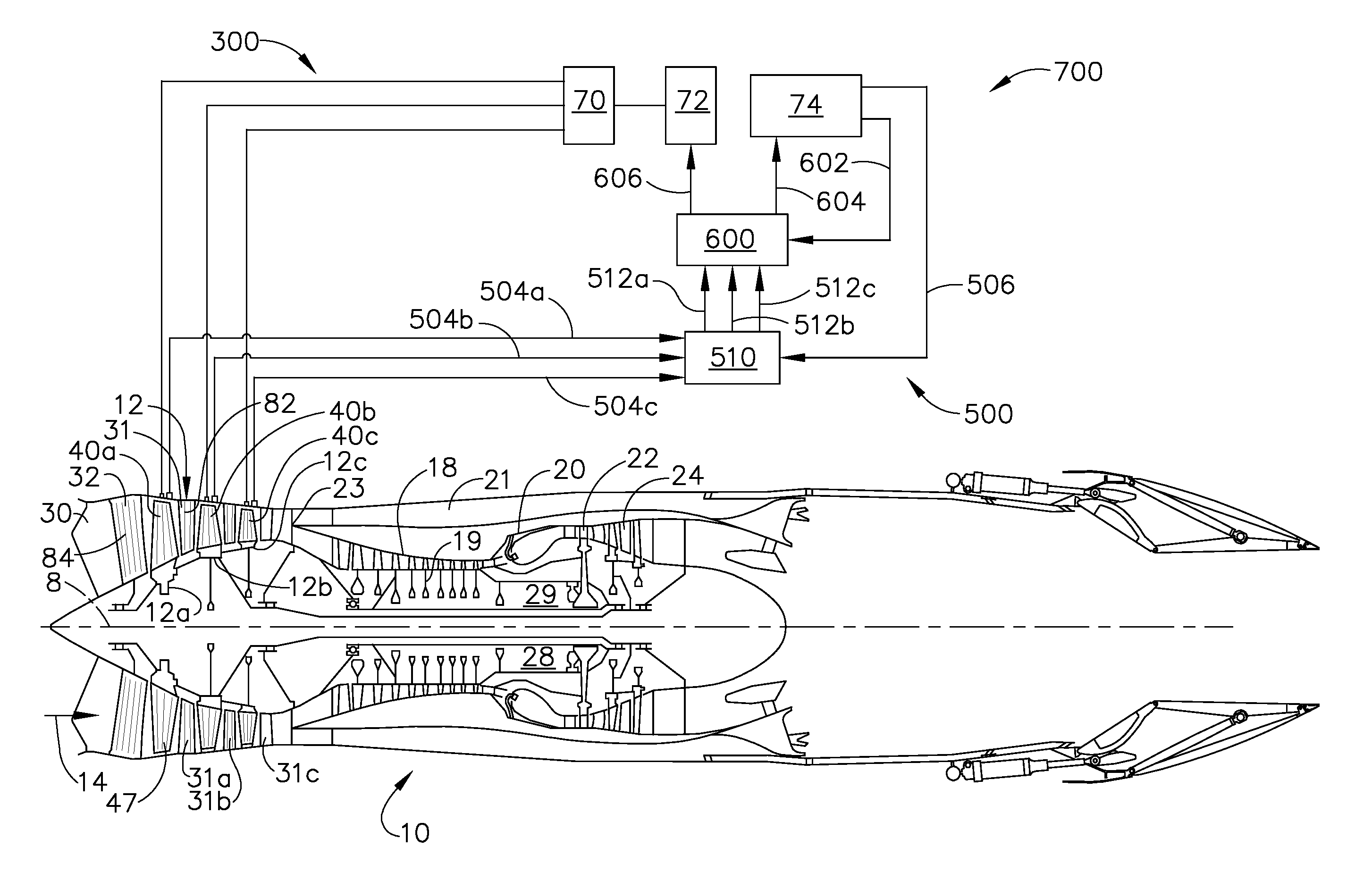
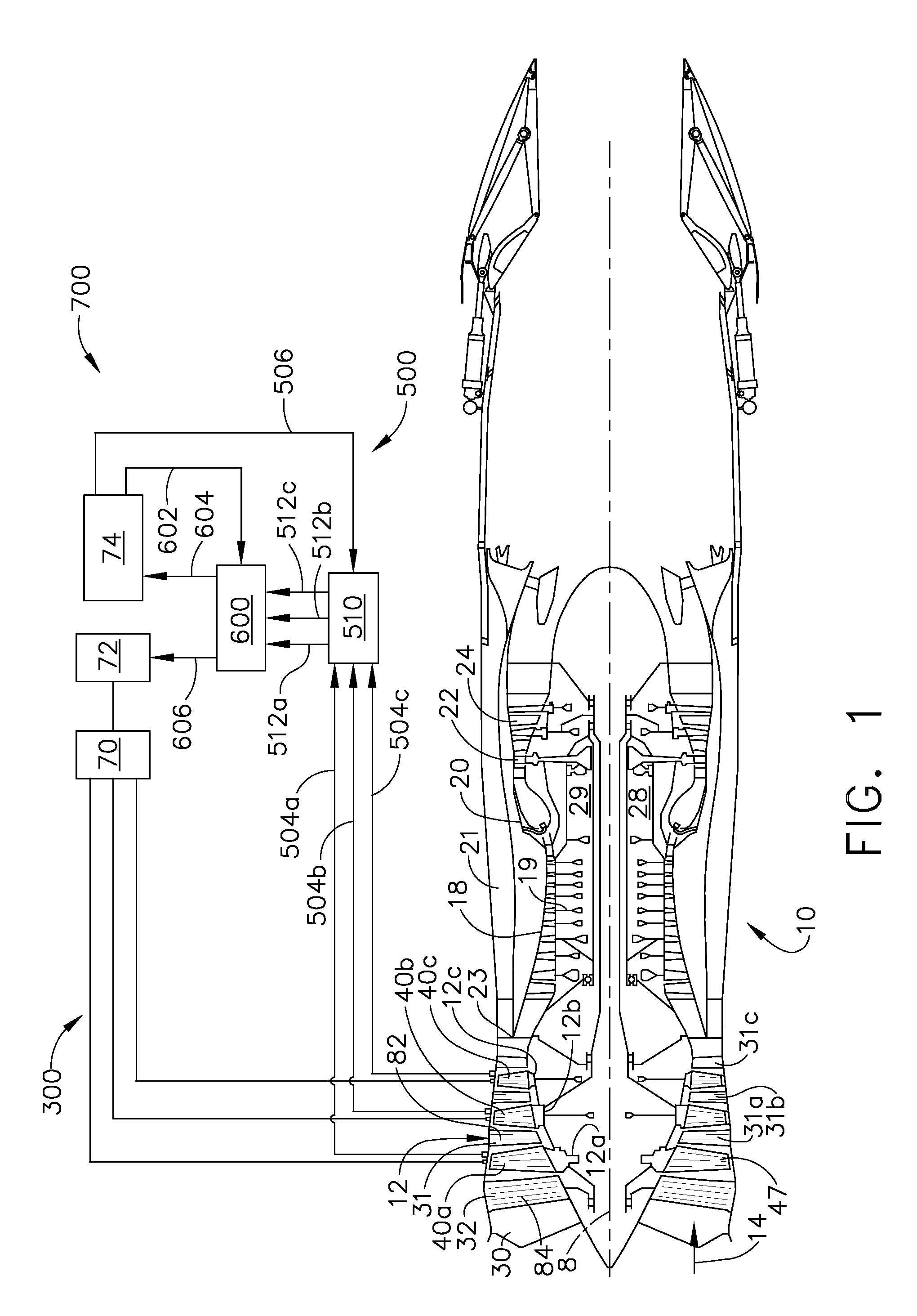
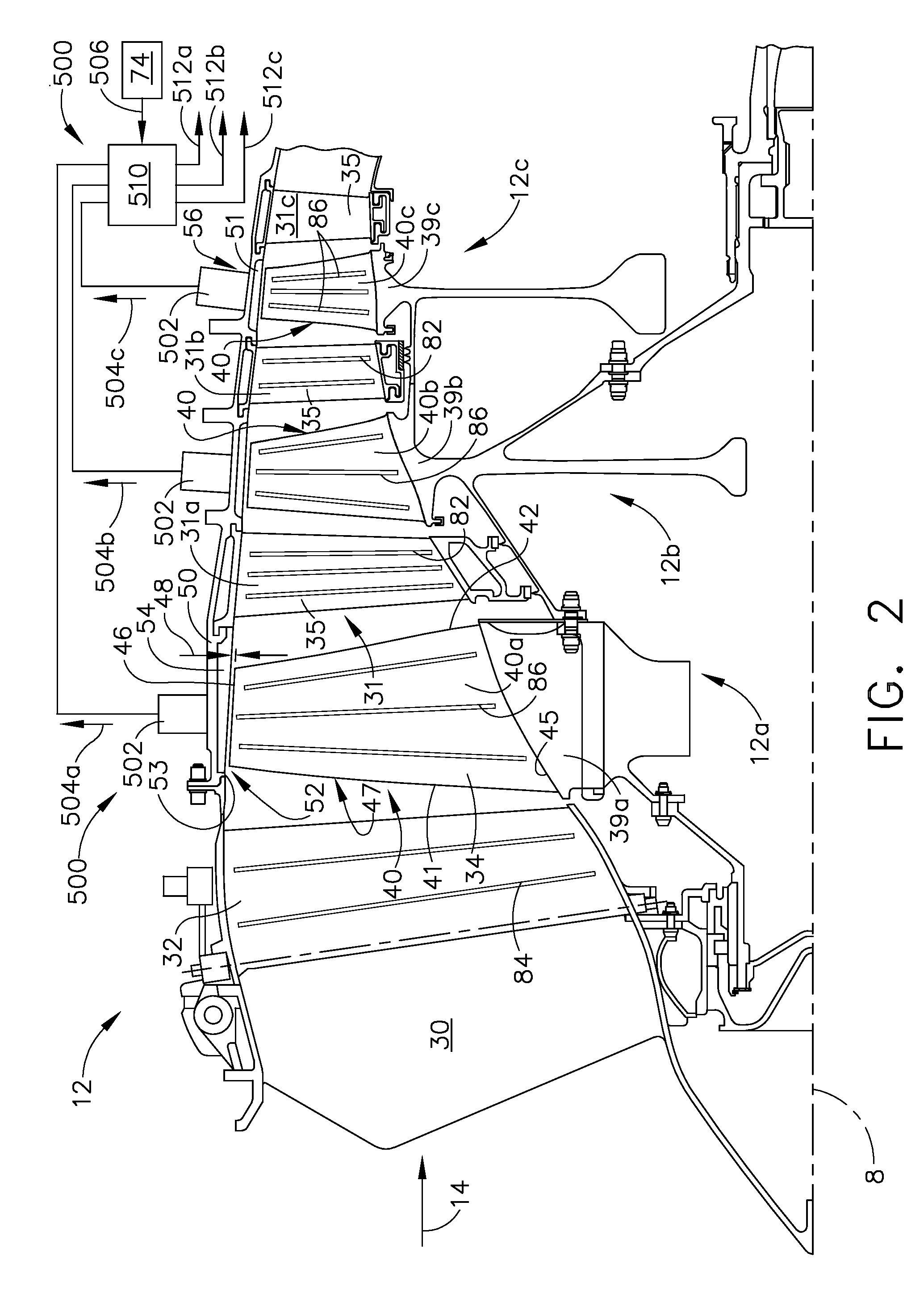
[0021]Referring to the drawings wherein identical reference numerals denote the same elements throughout the various views, FIG. 1 shows an exemplary turbofan gas turbine engine 10 incorporating an exemplary embodiment of the present invention. It comprises an engine centerline axis 8, fan section 12 which receives ambient air 14, a high pressure compressor (HPC) 18, a combustor 20 which mixes fuel with the air pressurized by the HPC 18 for generating combustion gases or gas flow which flows downstream through a high pressure turbine (HPT) 22, and a low pressure turbine (LPT) 24 from which the combustion gases are discharged from the engine 10. Many engines have a booster or low pressure compressor (not shown in FIG. 1) mounted between the fan section and the HPC. A portion of the air passing through the fan section 12 is bypassed around the high pressure compressor 18 through a bypass duct 21 having an entrance or splitter 23 between the fan section 12 and the high pressure compres...


PUM


Abstract

A compression system is disclosed, the compression system comprising a rotor having a plurality of blades arranged around a centerline axis, each blade having a blade airfoil and a blade tip, and at least one plasma actuator located on a blade. Exemplary embodiments of a detection system for detecting an instability in a compression system rotor and a mitigation system comprising at least one plasma actuator mounted on a blade to facilitate the improvement of the stability of the rotor are disclosed.

Description

BACKGROUND OF THE INVENTION[0001]This invention relates generally to gas turbine engines, and, more specifically, to a system for detection of an instability such as a stall in a compression system such as a fan or a compressor used in a gas turbine engine.[0002]In a turbofan aircraft gas turbine engine, air is pressurized in a compression system, comprising a fan module, a booster module and a compression module during operation. In large turbo fan engines, the air passing through the fan module is mostly passed into a by-pass stream and used for generating the bulk of the thrust needed for propelling an aircraft in flight. The air channeled through the booster module and compression module is mixed with fuel in a combustor and ignited, generating hot combustion gases which flow through turbine stages that extract energy therefrom for powering the fan, booster and compressor rotors. The fan, booster and compressor modules have a series of rotor stages and stator stages. The fan and...

Claims


Application Information

Patent Timeline
IPC IPC(8): F02C9/16F01D17/00F01D7/00
CPCF04D27/001F04D27/02F05D2270/172F05B2270/1081F04D29/526F05D2270/101F04D27/00F04D27/0246F04D29/522F15D1/12
Inventor WADIA, ASPI RUSTOMSADDOUGHI, SEYED GHOLAMALIAPPLEGATE, CLARK LEONARD
Owner GENERAL ELECTRIC CO
Why Eureka
Try Eureka