External fan duct casing in a turbomachine

a turbomachine and fan duct technology, which is applied in the direction of machines/engines, efficient propulsion technologies, liquid fuel engines, etc., can solve the problems of difficult access to the engine for maintenance operations, and achieve the effect of improving the transmission of forces, reducing the occurrence of carcass distortion, and impairing the performance of the turbo-jet engin

Active Publication Date: 2010-02-25
SN DETUDE & DE CONSTR DE MOTEURS DAVIATION S N E C M A
View PDF6 Cites 13 Cited by
  • Summary
  • Abstract
  • Description
  • Claims
  • Application Information

AI Technical Summary

Benefits of technology

[0011]The use of rigid beams, which confer on the framework its lattice pattern, makes it possible to improve the transmission of forces in the framework by distributing the absorption of forces over extended areas. The rigidity of this structure makes it possible to allow a portion of the shearing forces passing into the propulsive assembly to pass through said structure and thus to limit the transmission of these forces by the engine itself, which allows a significant reduction in the occurrence of distortion of the carcass, which generally im...

Problems solved by technology

In the prior art, in particular in the case of turbo-jet engines attached to the rear part of the fuselage of the aircraft, the external wall of the duct consists of a ...

Method used


Image

  • External fan duct casing in a turbomachine
  • External fan duct casing in a turbomachine

Examples


Embodiment Construction

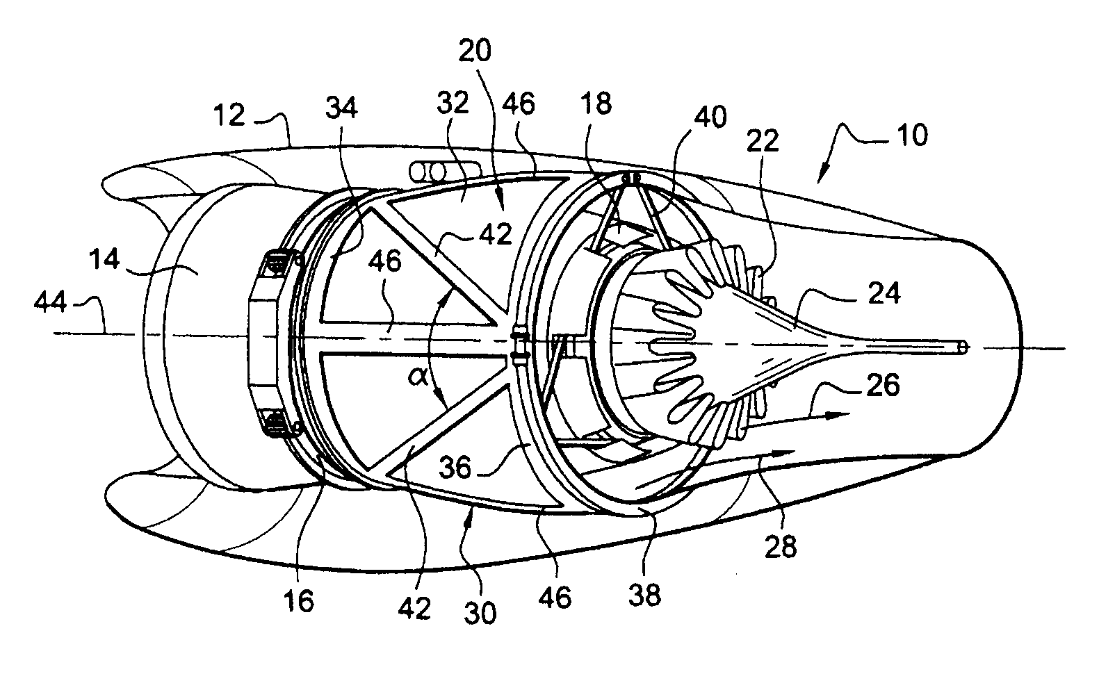
[0013]Advantageously, the lattice framework comprises beams parallel to the axis and / or beams inclined relative to the axis, which connect the upstream annular flange to the downstream annular flange, and which are regularly distributed about the axis.

[0014]According to a first variant of the invention, the lattice framework comprises rigid beams inclined relative to the axis which divide the casing into areas of substantially triangular shape and of substantially equal dimensions, each of these beams having an upstream end fixed to the upstream annular flange and a downstream end fixed to the downstream annular flange.

[0015]This particularly simple zigzag lattice pattern is characterized by an excellent transmission of forces.

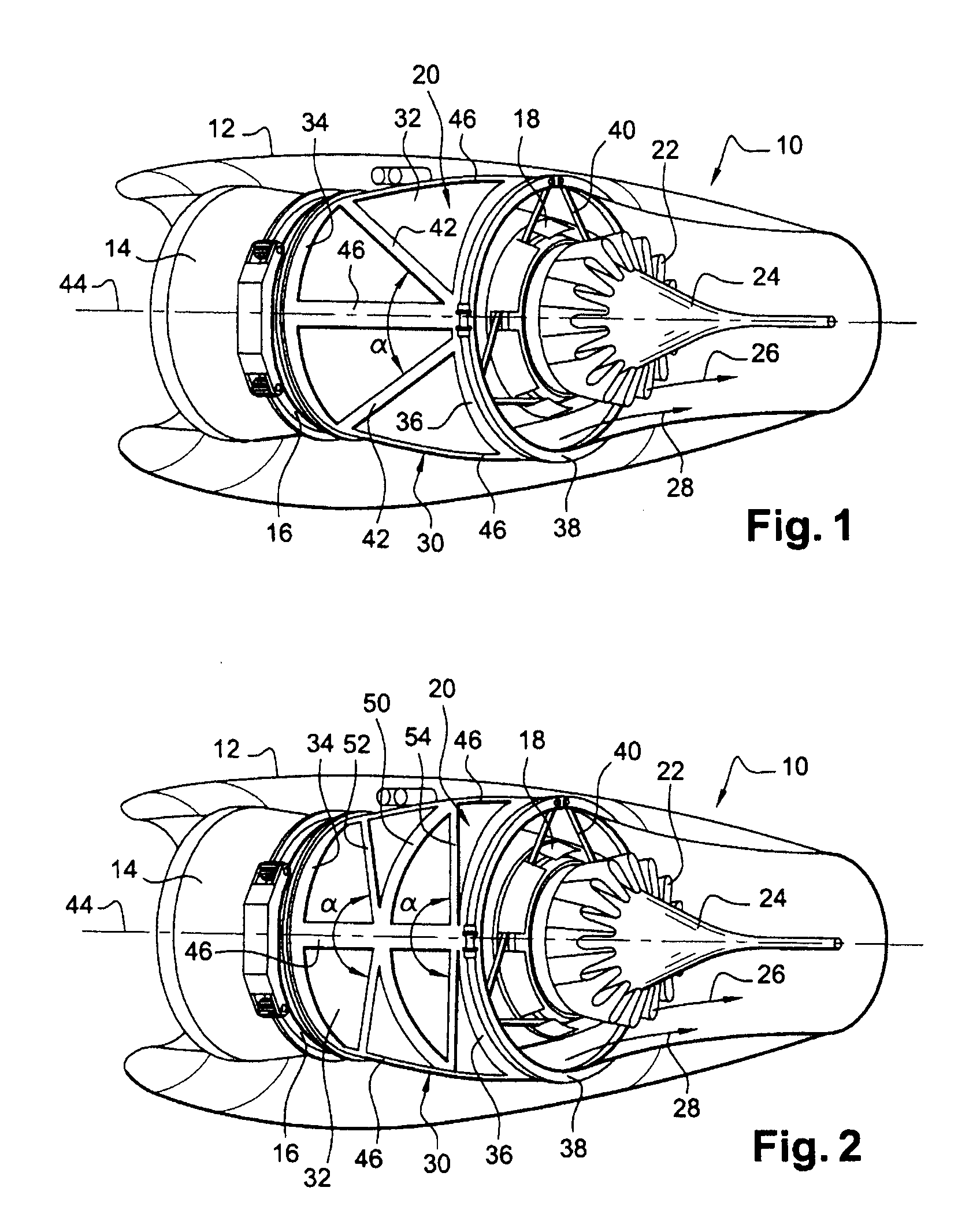
[0016]According to a further variant of the invention, the lattice framework comprises an intermediate reinforcing ring arranged coaxially between the upstream and downstream annular flanges and connected to the upstream and downstream beams by straight, rigid...


PUM


Abstract

Twin-flow turbo-jet engine, comprising a cylindrical casing externally defining an annular flow space for a secondary flow, wherein the cylindrical casing is formed from a lattice framework and from removable cowling panels fixed to the framework, said framework comprising an upstream annular flange for fixing to an intermediate housing, a downstream annular flange for connecting to an exhaust housing and rigid beams parallel or inclined relative to the axis of the turbo-jet engine, connecting the two flanges to one another.

Description

BACKGROUND OF THE INVENTION[0001]The present invention relates to a fan duct for a turbomachine such as an aircraft turbo-jet engine.[0002]The fan duct (often referred to as a “bypass duct”) of a turbomachine extends around the engine of the turbomachine, between the fan and the exhaust pipe, and comprises two substantially cylindrical coaxial walls which define therebetween an annular flow space for one portion of the air drawn in by the fan, forming a cold flow or secondary flow. The other portion of the air drawn in by the fan passes into the engine of the turbomachine which comprises, from upstream to downstream, a compressor, a combustion chamber and a turbine, and forms the hot flow or primary flow.[0003]The internal wall of the duct is fixed at its upstream end to an intermediate housing of the turbomachine and is connected at its downstream end to an exhaust housing. It is shaped to surround the engine of the turbomachine at a short radial distance.[0004]The external wall of...

Claims


Application Information

Patent Timeline
IPC IPC(8): F01D25/24F01D25/28
CPCF01D25/24F02C7/20F05D2250/231Y02T50/672F05D2250/183F02K3/06Y02T50/60
Inventor DERENES JACKY, RAPHAEL MICHELDIJOUD DELPHINE, EDITHREGARD, SEBASTIEN
Owner SN DETUDE & DE CONSTR DE MOTEURS DAVIATION S N E C M A
Why Eureka
Try Eureka