

Laser Patterning of Glass Bodies
a laser patterning and glass body technology, applied in the field of laser patterning of glass bodies, can solve the problems of unfavorable micromachining process, undesirable effects, and residual heat accumulation in the bulk of remaining materials, and achieve the effect of improving the accuracy of the micromachining process
- Summary
- Abstract
- Description
- Claims
- Application Information
AI Technical Summary
Problems solved by technology
Method used
Image

Examples
example 1
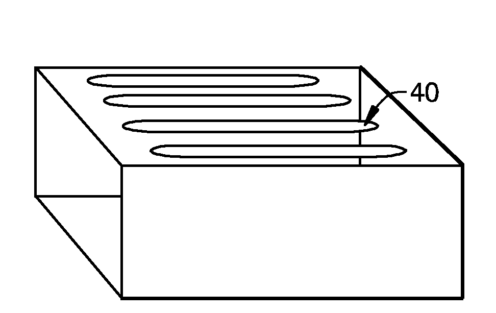
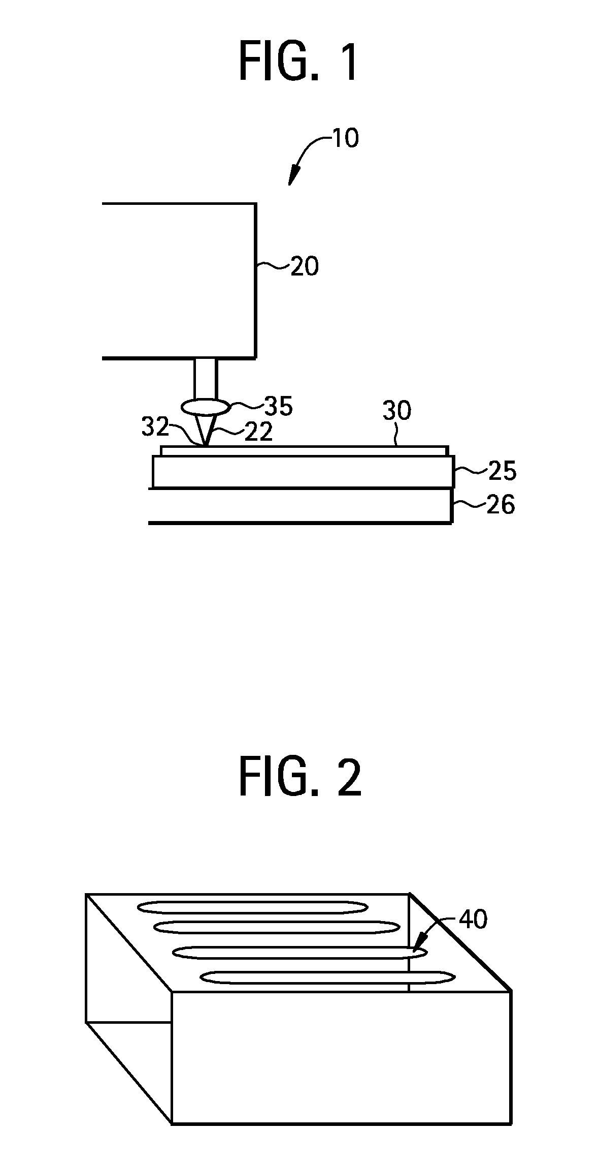
[0043]In this example, the glass body 30 was irradiated with a laser 20, at four different locations, each corresponding to one of four different beam velocities. More specifically, the laser output beam 22 was moved along the top surface of the glass body at a velocity V, where V was 15 mm / sec, 10 mm / sec, 5 mm / sec and 2 mm / sec. The composition of the cerium doped glass in this example was as follows:
(Mol %)SiO280.85Al2O31.21B2O312.44Na2O3.5CeO21TiO21
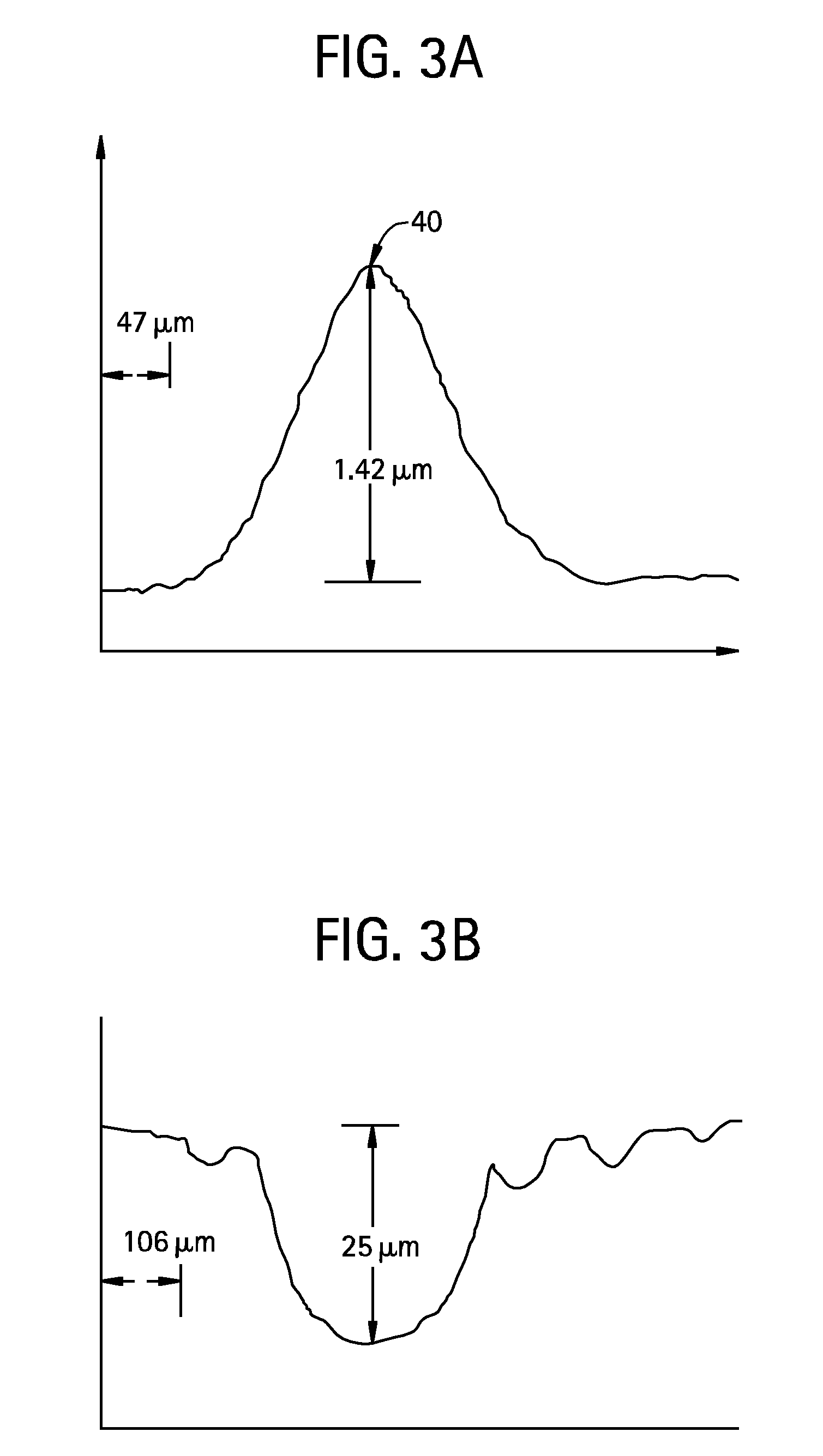
[0044]The following Table 1 summarizes the achieved results, which are illustrated in FIGS. 3A, 3C, 3E and 3G.
TABLE 1Ce-doped borosilicate glassvelocity V (mm / s)151052Resulting stress (psi)407101916304076Resulting Birefringence6.315.725.162.77(nm) for 0.7 thick glassswell peak h (μm)1.41.7835.5
[0045]The glass body 30 was then dipped in 50% HF acid for 5 minutes. The results are summarized in Table 2 and are shown in FIGS. 3B, 3D, 3F and 3H.
TABLE 2FIG. 3BFIG. 3DFIG. 3FFIG. 3Hetched depth (μm)2525140164
[0046]More specifically, FIGS. 3A, 3...
example 2
[0052]In this example, a glass body 30 was irradiated with a 3W CO2 laser 20, at two different locations. The composition of the glass body in this example was as follows:
(Mol %)SiO281B2O313Al2O32
[0053]At both locations the laser output beam 22 was moved along the top surface of the glass body at a velocity V=5 mm / sec. The laser output beam 22 spot size was about 150 μm. The glass body was then cut in half, resulting in two identical glass samples, each containing one laser beam irradiated area. One of the glass samples was annealed prior to etching and another was not annealed prior to etching. As in the previous example, the etching step was performed with a HF acid. The resulting depression after etch was −8.7 μm deep for a glass sample that was not annealed, and for partially annealed glass the depression was −3 μm deep. Again, we observed that annealing reduced the depth of the etched depression. Thus, in order to achieve maximum depression depth (without additional reduction i...
example 3
[0054]In this example, an iron-doped glass body 30 was irradiated with an 810 nm, CW laser 20, at two different locations. The composition of the glass body in this example was as follows:
(Mol %)SiO282.28B2O38.13Al2O31.21Na2O5.38Fe2O31TiO22
The laser power and resulting birefringence of swells 40 are tabulated below in Table 4.
TABLE 4Corresponding figureFIG. 5aFIG. 5bFIG. 5cFIG. 5dFIG. 5eFIG. 5fpower W1414121288stress, psi18,14009783053000Birefringence,279.40150.7081.60nm for 0.7mm glassSamplenoyesnoyesnoyesannealed50% HF / 5 minyesyesyesyesyesyesetched depth−3523−3312−272.3umcenter bump in2615etch cavity
In Table 4 the negative number corresponding to the etch depth means that the etched hole or groove is below the surface of the glass. Positive etch depth corresponds to the (at least partially) annealed examples, which indicate that no depression was formed by the etching process. In some glass bodies, the grove or hole contained a central “bump”-i.e., a raised area in the center and ...
PUM
| Property | Measurement | Unit |
|---|---|---|
| height | aaaaa | aaaaa |
| velocity | aaaaa | aaaaa |
| absorption coefficient | aaaaa | aaaaa |
Abstract
Description
Claims
Application Information