
Laser patterning of conductive films for electro-active lenses

a technology of electro-active lenses and conductive films, which is applied in the field of laser patterning of conductive films for electro-active lenses, can solve the problems of compromising the structural integrity of the lens, ophthalmic lenses and spectacle lenses in particular, and cosmetically undesirable seal rings of visible seal rings

Active Publication Date: 2013-08-15
MITSUI CHEM INC
View PDF1 Cites 24 Cited by
  • Summary
  • Abstract
  • Description
  • Claims
  • Application Information

AI Technical Summary

Benefits of technology

The invention provides a process for creating electro-active lenses that can be customized for different patent text describes a technology that allows for the creation of eyeglass lenses that can be customized for different patients, styles of glasses, and tint transmission. The technology also allows for the fabrication of a semi-finished lens blank that can be further shaped and polished for the patient's specific needs. The lenses can be easily edged into the shape of popular electronic eyeglass frames without detracting from their appearance and can be powered by a small battery integrated into the frame.

Problems solved by technology

These visible seal rings are cosmetically undesirable to consumers.
Such structures, however, are not viable for ophthalmic lenses and spectacle lenses in particular.
To date, methods and structures designed to reduce the visibility of any liquid optical material seal in an ophthalmic lens often compromise the structural integrity of the lens.
As such, conventional methods for processing such lenses (e.g., conventional methods for cutting and edging a lens) can cause containment of the liquid optical material to be disturbed and can also disrupt the ability to alter the refractive index of the liquid optical material electronically.
Consequently, many prior art electro-active lenses are not commercially viable products.
While masking the deposition of ITO may achieve the desired goal of reducing electrical shorting, the inventors have found that it has a drawback in that the non-uniformity of the coatings may be highly visible in a finished lens, especially one that has been AR coated.
This non-uniform appearance of the lens will be unacceptable in a commercially product.

Method used


Image

  • Laser patterning of conductive films for electro-active lenses
  • Laser patterning of conductive films for electro-active lenses
  • Laser patterning of conductive films for electro-active lenses

Examples


Embodiment Construction

[0045]It is understood that the invention is not limited to the particular methodology, protocols, etc., described herein, as these may vary as the skilled artisan will recognize. It is also to be understood that the terminology used herein is used for the purpose of describing particular embodiments only, and is not intended to limit the scope of the invention. It also is to be noted that as used herein and in the appended claims, the singular forms “a,”“an,” and “the” include the plural reference unless the context clearly dictates otherwise. Thus, for example, a reference to “a finger” is a reference to one or more fingers and equivalents thereof known to those skilled in the art.

[0046]Unless defined otherwise, all technical terms used herein have the same meanings as commonly understood by one of ordinary skill in the art to which the invention pertains. The embodiments of the invention and the various features and advantageous details thereof are explained more fully with refer...


PUM

PropertyMeasurementUnit
Lengthaaaaaaaaaa
Lengthaaaaaaaaaa
Widthaaaaaaaaaa

Abstract

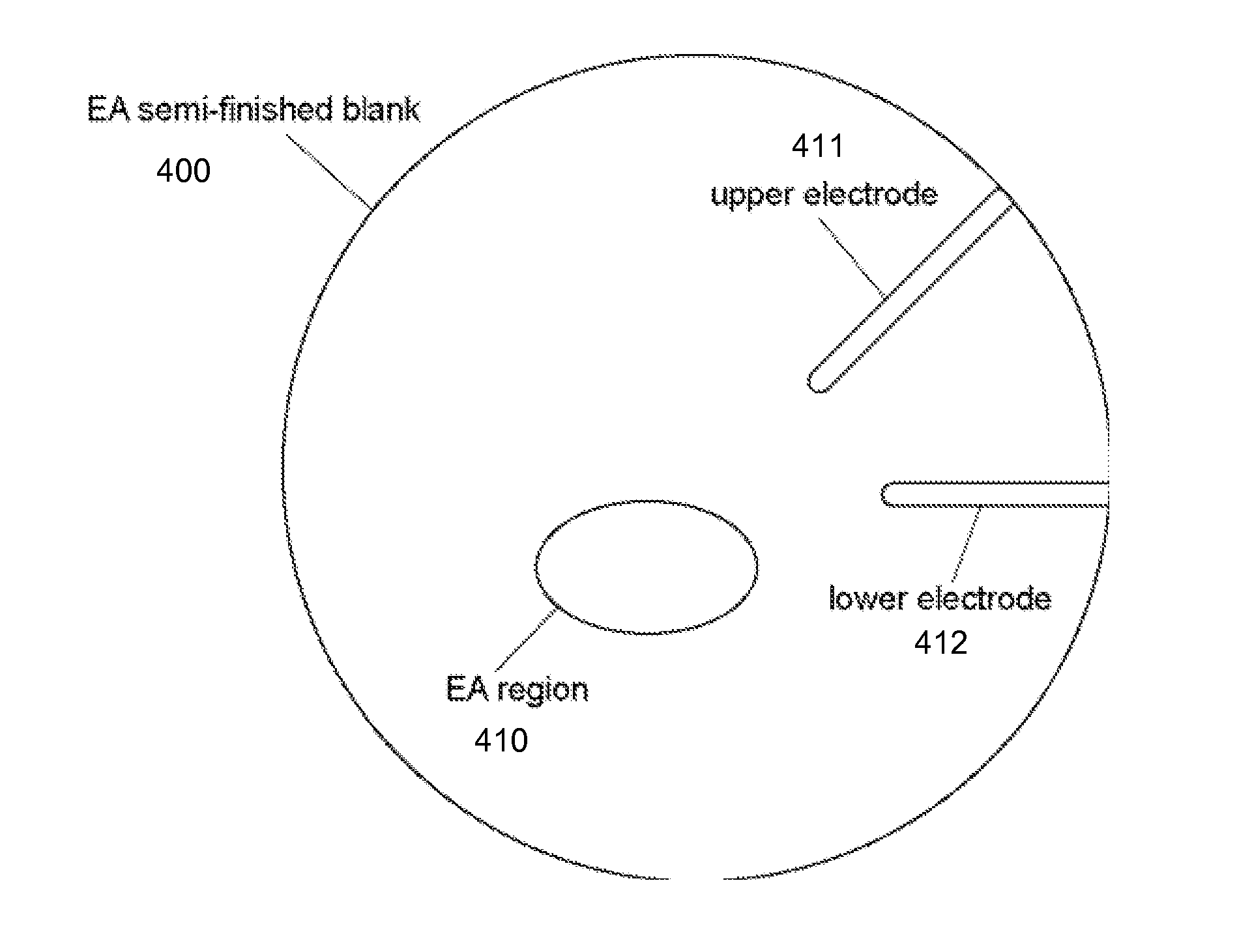
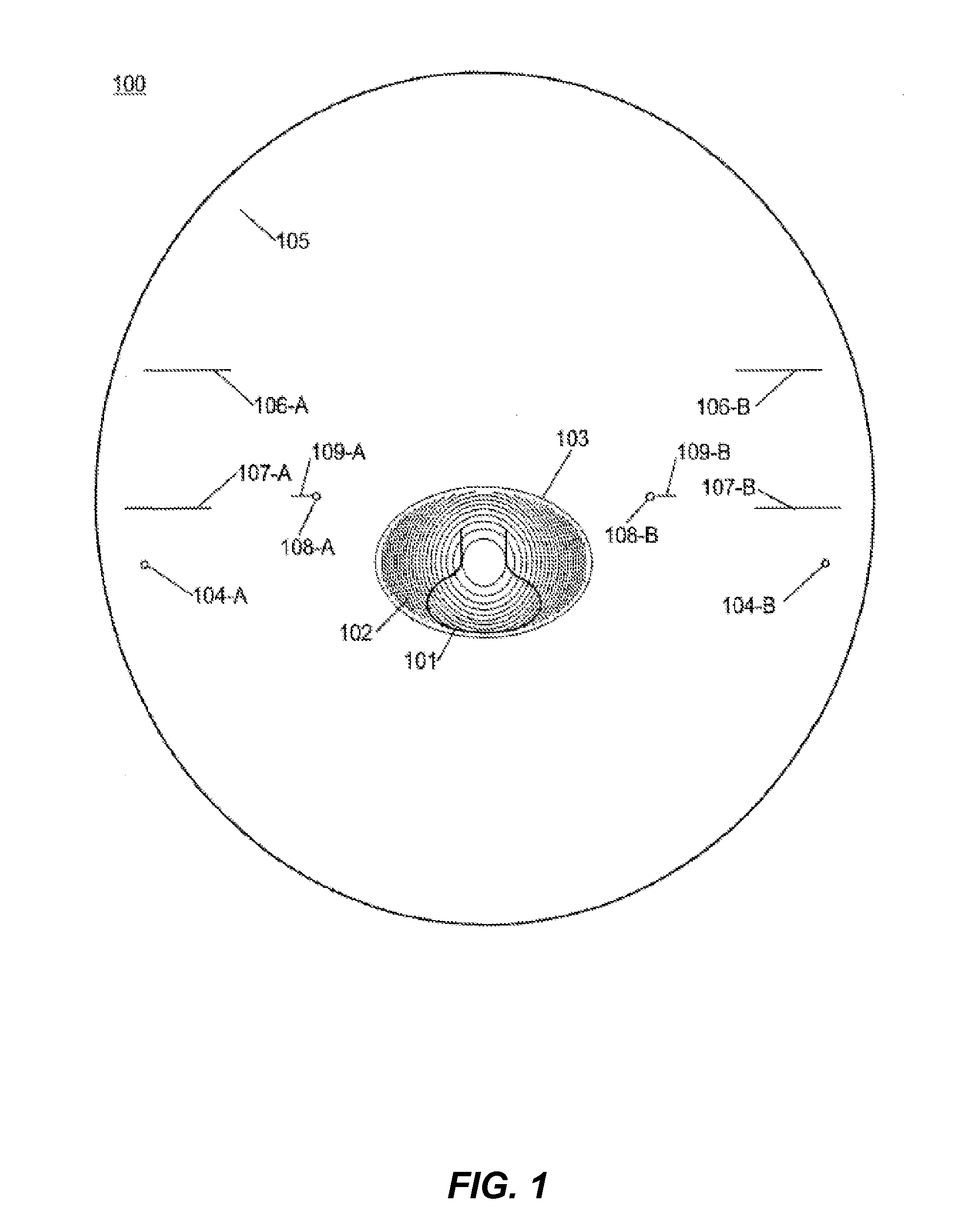
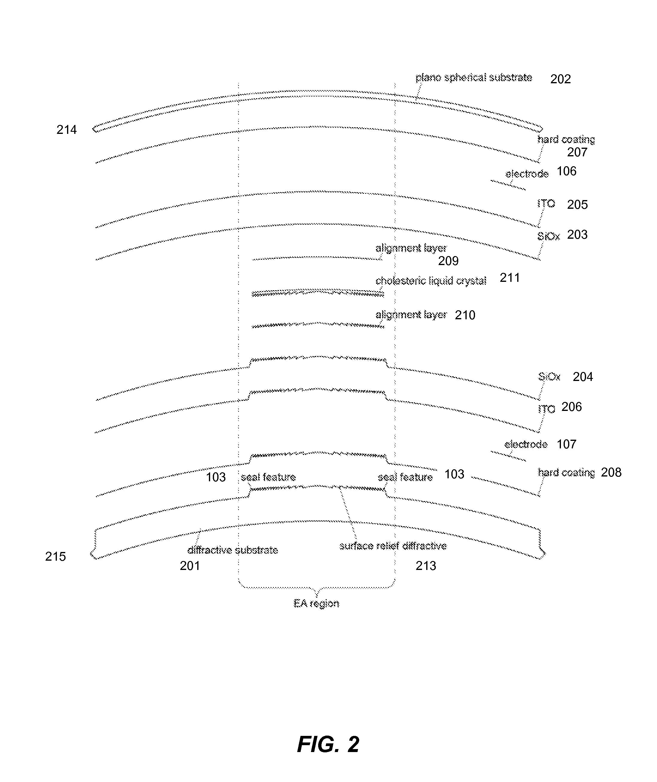
Systems and methods for manufacturing electro-active lenses including a peripheral edge, a discrete electro-active region, and at least two substrates. The at least two substrates include a layer of a transparent conductive material, that is laser cut to isolate regions required for establishing an electrical connection between the peripheral edge of the lens, from regions not required for establishing an electrical connection. Isolating the regions of the transparent conductive material required for establishing an electrical connection may include cutting patterns around an electrode of each of the substrates. The regions not required for establishing an electrical connection may be further cut into sections, which may be substantially band-shaped.

Description

CROSS-REFERENCES TO RELATED APPLICATIONS[0001]This application claims benefit under 35 U.S.C. §119(e) of U.S. provisional patent application No. 61 / 595,720, filed on Feb. 7, 2012, the entire disclosure of which is incorporated herein by reference for all purposes.[0002]This application is related to U.S. patent application Ser. No. 12 / 408,973, published as U.S. 2009 / 0256977, the entire disclosure of which is incorporated herein by reference for all purposes.BACKGROUND OF THE INVENTION[0003]Electro-active lenses generally include a liquid optical material (e.g., liquid crystal) encapsulated or contained by one or more solid, transparent optical materials. Conventional methods and structures for containing the liquid optical material often result in a visible seal ring on the lens indicating the positioning of the liquid optical material. These visible seal rings are cosmetically undesirable to consumers.[0004]In conventional liquid crystal displays (LCDs), sealing features can typica...

Claims


Application Information

Patent Timeline
IPC IPC(8): G02F1/29
CPCG02C7/083G02F1/29Y10T83/0341B29D11/00817
Inventor HADDOCK, JOSHUA N.WILLEY, CHARLES
Owner MITSUI CHEM INC
Learn More