Hydrogen generating system and operating method therefor

Active Publication Date: 2010-03-04
HONDA MOTOR CO LTD
View PDF3 Cites 13 Cited by
  • Summary
  • Abstract
  • Description
  • Claims
  • Application Information

AI Technical Summary

Benefits of technology

[0012]The present invention has been made to resolve the above types of problems, and an object of the present invention is to provide a hydrogen generating system and an operating method therefor, which can efficiently eliminate impurity oxygen from hydrogen generated by water electrolysis, and which is capable of obtaining high-purity hydrogen both easily and reliably.
[0016]According to the present invention, upon start-up of the water electrolysis unit, because the pressure of the generated hydrogen is low, the impurity oxygen contained within the hydrogen is high. Accordingly, by discharging such low purity hydrogen to the outside of the hydrogen supply passage via the back-pressure valve mechanism, which is set to the first back pressure, the low purity hydrogen can be eliminated reliably from the water electrolysis unit.
[0017]Next, after the oxygen concentration within the hydrogen has been decreased, high-pressure hydrogen is extracted into the hydrogen supply passage via the back-pressure valve mechanism, which is set to a second back pressure at a higher pressure than the first back pressure. Consequently, high-pressure hydrogen of high-purity, from which impurity oxygen has been eliminated, can be supplied reliably and efficiently to the hydrogen supply passage.

Problems solved by technology

Hence, there is a concern that such impurity oxygen will act as a catalytic poison in the fuel cell.
However, with the aforementioned Japanese Laid-Open Patent Publication No. 2007-100204, in particular, it is difficult for impurity oxygen contained within the hydrogen, which is generated upon start-up of the high-pressure hydrogen producing apparatus, to be eliminated reliably.
Therefore, it has been necessary for a reaction system to be used for removing impurity oxygen generated upon start-up, which makes the structure of the apparatus complicated.

Method used


Image

  • Hydrogen generating system and operating method therefor
  • Hydrogen generating system and operating method therefor
  • Hydrogen generating system and operating method therefor

Examples


first embodiment

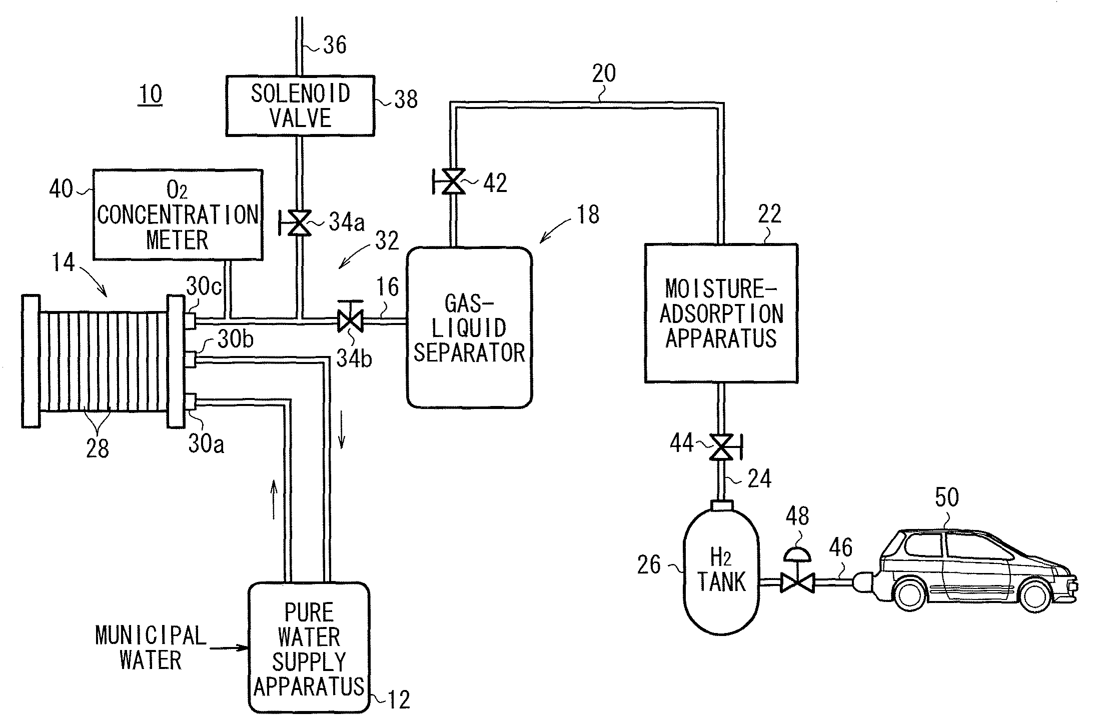
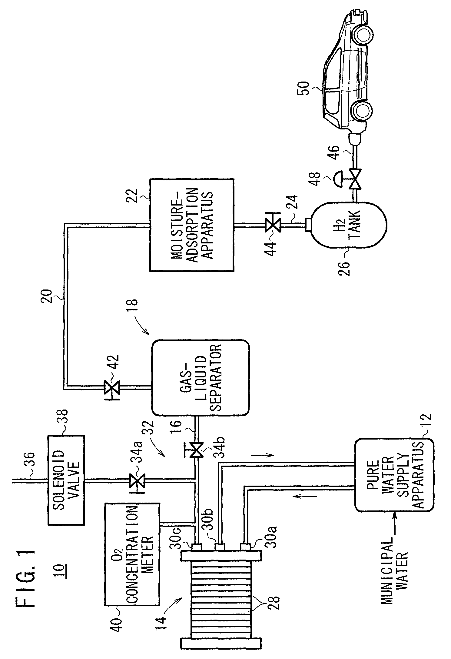
[0024]As shown in FIG. 1, a hydrogen generating system 10 to which an operating method according to the present invention is applied is equipped with a water electrolysis apparatus (water electrolysis unit) 14, which is supplied with pure water produced from municipal water by a pure water supply apparatus 12, and which produces high-pressure hydrogen by performing electrolysis on the pure water, a gas-liquid separator (gas-liquid separating unit) 18 that removes moisture contained in the high-pressure hydrogen delivered from the water electrolysis apparatus 14 to a hydrogen lead-out passage 16, a moisture-adsorption apparatus 22 for adsorbing and eliminating moisture contained within the hydrogen supplied from the gas-liquid separator 18 to a hydrogen supply passage 20, and a hydrogen tank 26, which is capable of retaining the hydrogen (dry hydrogen) that is delivered out to a dry hydrogen supply passage 24 connected to the moisture-adsorption apparatus 22. Incidentally, the hydrog...

third embodiment

[0052]FIG. 4 is an outline structural schematic drawing of a hydrogen generating system 70 to which an operating method according to the present invention is applied.

[0053]In the water electrolysis apparatus 14 constituting the hydrogen generating system 70, a back-pressure valve mechanism 72 is disposed in the pipe 30c, which forms the hydrogen outlet. The back-pressure valve mechanism 72 is equipped with a first back-pressure valve 34a and a pressure-reducing valve 74 that together make up a first back-pressure setting mechanism, and a second back-pressure valve 34b that makes up a second back-pressure setting mechanism.

[0054]According to the third embodiment, the first back-pressure valve 34a and the pressure-reducing valve 74 are provided as the first back-pressure setting mechanism, and together therewith, the set pressure of the first back-pressure valve 34a and the pressure-reducing valve 74 is set, for example, at 1 MPa. Owing thereto, in particular, the solenoid valve 38 ca...


PUM

PropertyMeasurementUnit
Pressureaaaaaaaaaa
Concentrationaaaaaaaaaa

Abstract

A hydrogen generating system is equipped with a water electrolysis unit for producing hydrogen by performing electrolysis on pure water supplied from a pure water supply apparatus, with a back-pressure valve mechanism disposed in a hydrogen outlet port of the water electrolysis unit. The back-pressure valve mechanism is equipped with a first back-pressure valve, which sets a first back pressure, for discharging hydrogen to the outside of a hydrogen supply passage, and a second back-pressure valve, which sets a second back pressure at a higher pressure than the first back pressure, for extracting high-pressure hydrogen into the hydrogen supply passage.

Description

BACKGROUND OF THE INVENTION[0001]1. Field of the Invention[0002]The present invention relates to a hydrogen generating system, which is equipped with a water electrolysis unit for performing electrolysis on water, such that when hydrogen generated by the water electrolysis unit is developed into high-pressure hydrogen at or above a predetermined pressure, the high-pressure hydrogen is extracted into a hydrogen supply passage via a back-pressure valve mechanism, and also relates to an operating method therefor.[0003]2. Description of the Related Art[0004]Recently, there has been proposed systems that supply electrical power or motive power using hydrogen as a fuel, for example, a fuel cell system or the like. For manufacturing hydrogen as a fuel, a water electrolysis apparatus is used, by which water is subjected to electrolysis in order to produce hydrogen (and oxygen).[0005]In such a water electrolysis apparatus, generally, during electrolysis, oxygen is diffused through an electro...

Claims


Application Information

Patent Timeline
IPC IPC(8): C25B1/12C25B9/00
CPCC25B1/12Y02E60/366C25B15/02C25B1/04C25B9/05Y02E60/36
Inventor OKABE, MASANORINAKAZAWA, KOJITARUYA, KENJI
Owner HONDA MOTOR CO LTD
Why Eureka
Try Eureka