
Mechanism for doubling soap dispensing amount of automatic soap dispenser

a technology of automatic soap dispenser and soap dispenser, which is applied in the field of automatic soap dispenser dispenser and soap dispenser mechanism, can solve the problem of not allowing the soap dispenser amount to return to a normal level, and achieve the effect of small resistan

Inactive Publication Date: 2010-03-04
CHEN JAN SUN
View PDF3 Cites 2 Cited by
  • Summary
  • Abstract
  • Description
  • Claims
  • Application Information

AI Technical Summary

Benefits of technology

[0007]In order to overcome the shortcomings of the prior art, the present invention provides a mechanism for doubling a soap dispensing amount of an automatic soap dispenser, so that the soap dispensing amount can be flexibly or constantly increased to suit different user needs.
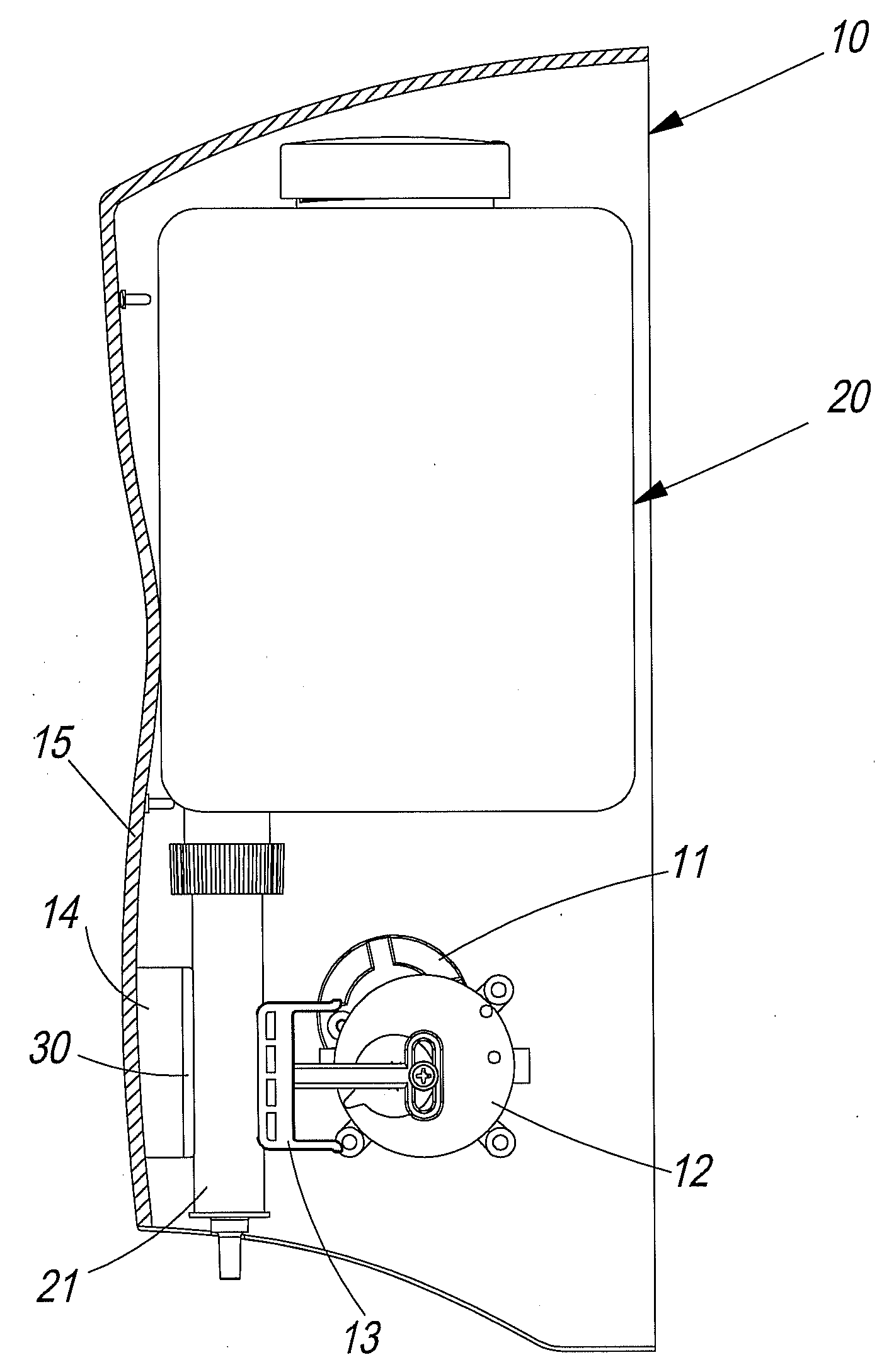
[0008]The aforesaid mechanism for doubling a soap dispensing amount of an automatic soap dispenser comprises: a driving device disposed in a soap dispenser and including a motor and a speed reducer having an output end coupled with a pushing element; a resisting element disposed on an inner surface of a casing of the soap dispenser, wherein the inner surface is on a forward moving side of the pushing element; and a soap container having a bottom connected with a discharge tube located between the pushing element and the resisting element. The mechanism for doubling a soap dispensing amount is characterized in that a pad is coupled to a side of the resisting element facing the pushing element so as to be adjacent to an outer surface of a middle rubber section of the discharge tube. Since the resisting element is extended in the presence of the pad so as to get closer to the outer surface of the middle rubber section of the discharge tube than without the pad, or even come in contact with said outer surface, liquid soap will be dispensed as soon as the pushing element is moved towards the resisting element until the pushing element completes a moving cycle. Hence, without having to modify an existing soap dispensing mechanism of the soap dispenser and the moving cycle of the pushing element, the soap dispending amount of the existing soap dispensing mechanism can be doubled by the present invention. For example, the present invention can increase the soap dispensing amount of the existing soap dispensing mechanism from 1 cc to 2 cc.
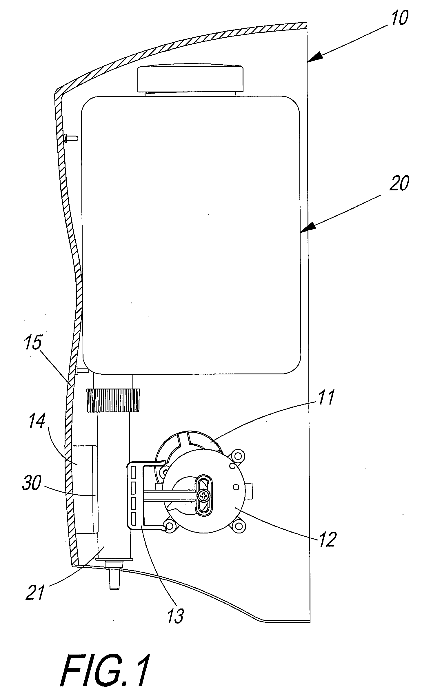
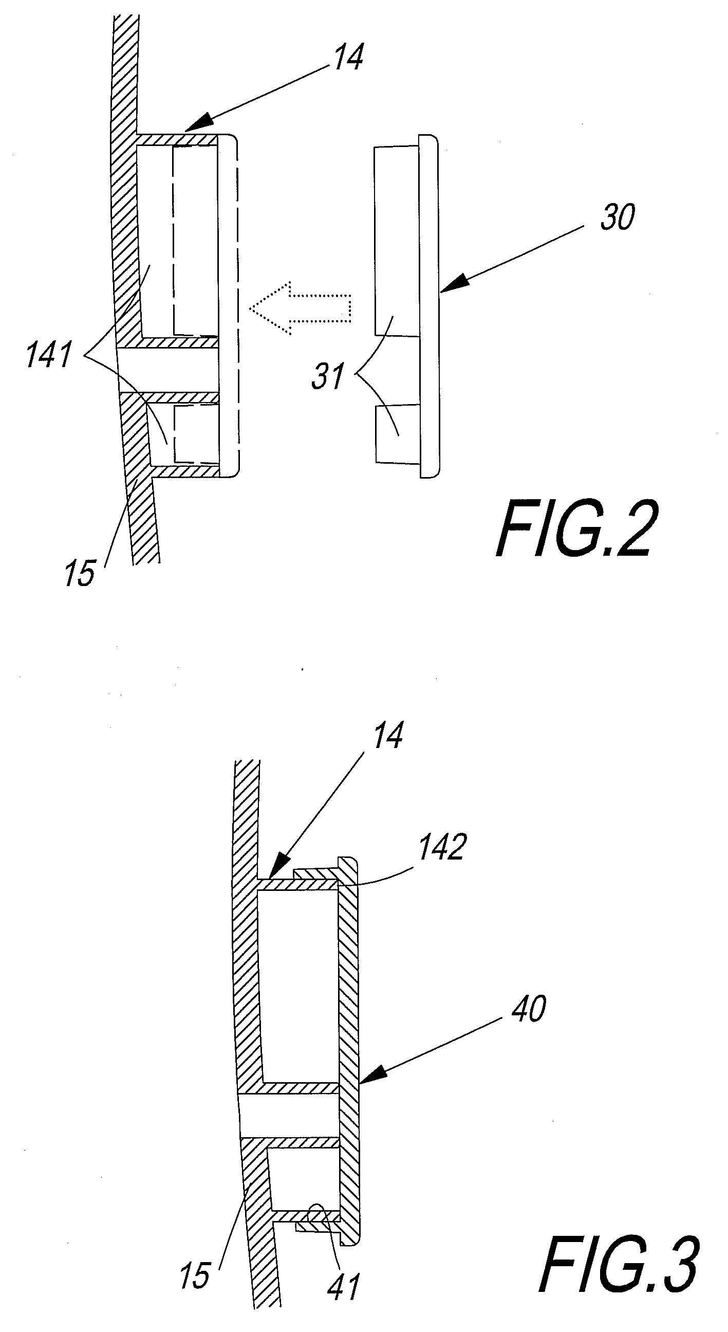
[0009]In the aforesaid mechanism for doubling a soap dispensing amount of an automatic soap dispenser, the pad is preferably coupled to the resisting element in a detachable manner, for example by being engaged with or fastened to the resisting element, so that a user can determine whether it is necessary to increase the soap dispensing amount according to such factors as the desired amount of liquid soap to be used and viscosity of the liquid soap. When it is desired to increase the soap dispending amount, the pad can be conveniently and rapidly coupled to the resisting element; otherwise, the pad need not be installed or can be removed from the resisting element.
[0011]In the aforesaid mechanism for doubling a soap dispensing amount of an automatic soap dispenser, the middle rubber section of the discharge tube connected to the soap container preferably has a hardness of HS50 to HS55 (Shore Hardness), so that the discharge tube produces a relatively small resistance and deforms to a larger extent when compressed jointly by the pushing element, the resisting element and the pad, thereby doubling the soap dispending amount.

Problems solved by technology

However, the latter approach does not allow the soap dispensing amount to return to a normal level, as can be achieved with the detachable pad mentioned above.

Method used


Image

  • Mechanism for doubling soap dispensing amount of automatic soap dispenser
  • Mechanism for doubling soap dispensing amount of automatic soap dispenser
  • Mechanism for doubling soap dispensing amount of automatic soap dispenser

Examples


Embodiment Construction

[0016]Referring to FIG. 1, according to a preferred embodiment of a mechanism for doubling a soap dispensing amount of a soap dispenser of the present invention, a soap dispenser 10 comprises a driving device disposed therein, wherein the driving device includes a motor 11 and a speed reducer 12 having an output end coupled with a pushing element 13. The mechanism further comprises a resisting element 14 provided on an inner surface of a casing 15 of the soap dispenser 10, wherein the inner surface is on a forward moving side of the pushing element 13; a soap container 20 having a bottom connected with a discharge tube 21 located between the pushing element 13 and the resisting element 14; and a pad 30, in the form of a plate or a block, coupled to a side of the resisting element 14 facing the pushing element 13 so as to be adjacent to an outer surface of the discharge tube 21.

[0017]Referring to FIGS. 2 and 3, the pad 30 is preferably coupled to the resisting element 14 in a detacha...


PUM


Abstract

A mechanism for doubling a soap dispensing amount of an automatic soap dispenser includes: a speed reducer disposed inside a soap dispenser, driven by a motor and coupled with a pushing element; a resisting element provided on an inner surface of the soap dispenser that is on a forward moving side of the pushing element; and a soap container connected with a discharge tube located between the pushing element and the resisting element. A pad is coupled to a side of the resisting element facing the pushing element so as to be adjacent to an outer surface of the discharge tube, thereby increasing the time the discharge tube is jointly compressed by the pushing element and the resisting element. Thus, the soap dispensing amount can be doubled without having to modify an existing soap dispensing mechanism of the soap dispenser and a moving cycle of the pushing element.

Description

BACKGROUND OF THE INVENTION[0001]1. Technical Field[0002]The present invention relates to a soap dispensing mechanism of an automatic soap dispenser, and more particularly, to a mechanism for doubling a soap dispensing amount.[0003]2. Description of Related Art[0004]Automatic soap dispensers, mostly sensor-actuated, are widely used at homes as well as in public places for dispensing liquid soap in a sanitary way as there is no need to contact the liquid soap dispensing devices.[0005]Soap is dispensed from an automatic soap dispenser by an electrically driven compression mechanism pushing or compressing a soap container loaded with liquid soap or a discharge tube. The course or time of compression can be set so as to discharge a constant amount of liquid soap. However, the dispensing of liquid soap at a constant amount cannot satisfy all user needs. For instance, some believe that only with a large amount of liquid soap can a good cleaning effect be achieved in a filthy environment; ...

Claims


Application Information

Patent Timeline
IPC IPC(8): B65D37/00
CPCA47K5/1215
Inventor CHEN, JAN SUN
Owner CHEN JAN SUN
Learn More