Inner Tube with Film

a technology of inner tubes and films, applied in the field of transportation systems, can solve the problems of significant energy loss, cost and jeopardize human lives, and inferior materials of wheel assemblies, and achieve the effects of reducing the number of conventional charging devices installed into reducing the cost and jeopardizing human lives, and improving the cruising continuality of the energy consuming body,

Inactive Publication Date: 2010-03-04
WUHAN RUNLIN SCI & TECH DEVMENT
View PDF17 Cites 19 Cited by
  • Summary
  • Abstract
  • Description
  • Claims
  • Application Information

AI Technical Summary

Benefits of technology

[0021]Generally, tires of different purposes have different stuffing materials. The stuffing materials according to the present invention have a number of apparent advantages, first of all, the water-tightness property of rubber and plastic are much better than the air-tightness. And the cumbersome and laborious air-refilling process could be eliminated, at the same time, the turning radius of the landing portion are kept unchangeable, so that the turning resistance will be reduced as well.
[0069]What is more, a lot of conventional energy consuming objects, such as mobile phones, electrical means, home electrical appliances, could be charged according to this method. The conventional charging device installed into the energy consuming body could be eliminated. Furthermore, the present invention provides an intermediate approach to solve the electricity of the combustive engine. And such charging process could be arranged at a power consumption valley time.

Problems solved by technology

1. Poor security: the tires mounted to the wheel rim are subject to blowout accidents which cost and jeopardize human lives.
2. Inefficiency: as its name implied, efficiency refers to the working output of such wheel during a fixed period of time. For most pneumatic tires mounted to the wheel rim, the turning radius of such wheel is shortened in landing portion under a loaded pressure, however, the turning radius of remaining wheel portion are not shortened, instead, would been prolonged due to the increased pressure. As a result, the rotational wheel will have to overcome resistance force thus causing significant energy loss.
3. The wheel assembly is made of inferior materials, such as the air-tightness of the inner tube of the tire is not satisfied in most cases.
4. The structure of such wheel is not well designed, for example, the inner cavity and curvature of outer cover of the tire are not desired to prevent the turning radius of the wheel from being varied from time to time. And two side wall of outer cover of the tires are too high causing unnecessary raw material wasting.
5. Expensive costs: the landing circumferential surface of the tire outer cover is worn off easily, while two side walls of the outer cover are still of good shape, so the disposal of such tire is not an economic way.
6. Inconvenience: the tire inner tube should be refilled from time to time.
There are a plurality of drawbacks existed in prior art of transmission system, that is to say, the transmission system of vehicle wheels are not in an efficient way.
According to the wheel-axis mechanism and movable pulley mechanism, the conventional transmission designed is not appropriate.
Needless to say, the conventional method is not efficient.
What is more, other conventional wheel transmission method, such rotational fans, propellers of vessels and airplanes, and blade wheel of the fluid pump are subject to this inherent inefficiency.
However, the dynamic force is not transmitted in an accurate manner thus consuming considerable energy and causing energy waste.
In a long run, the friction between the tire and mechanical parts will reduce the life span of vehicle, and such design is not suitable for withstanding harsh conditions, such as not suitable for being mixed with water and mud.
In addition, if the tire is less stuffed, the tire will be softened, the shortened turning radius will cause the transmission effect deteriorated.
However, there are no such wheels applied in the motored vehicles.
For those transmission utilizing electrical means, there existed some problems to be solved, such as high energy consumption, poor endurance.
However, conventional energy supplying system comprises a plurality of drawbacks; first of all, the recharging and the refueling process are not safe.
Second, the charging process is time consuming.
Third, the cruising continuality of vehicles is limited, for example, the electrical vehicle can cruise no more than 100 miles after fully charged.
Fourth, the dynamic force is not sufficient.
After a continuous operation, the electrical energy stored within the electrical vehicle will be weakened thus limiting the speed of such vehicle.
Fifth, the energy sources are not universally applicable in different applications.
Sixth, the conventional storage battery comprises a plurality separate battery units which are not convenient and user friendly.

Method used


Image

  • Inner Tube with Film
  • Inner Tube with Film
  • Inner Tube with Film

Examples


Embodiment Construction

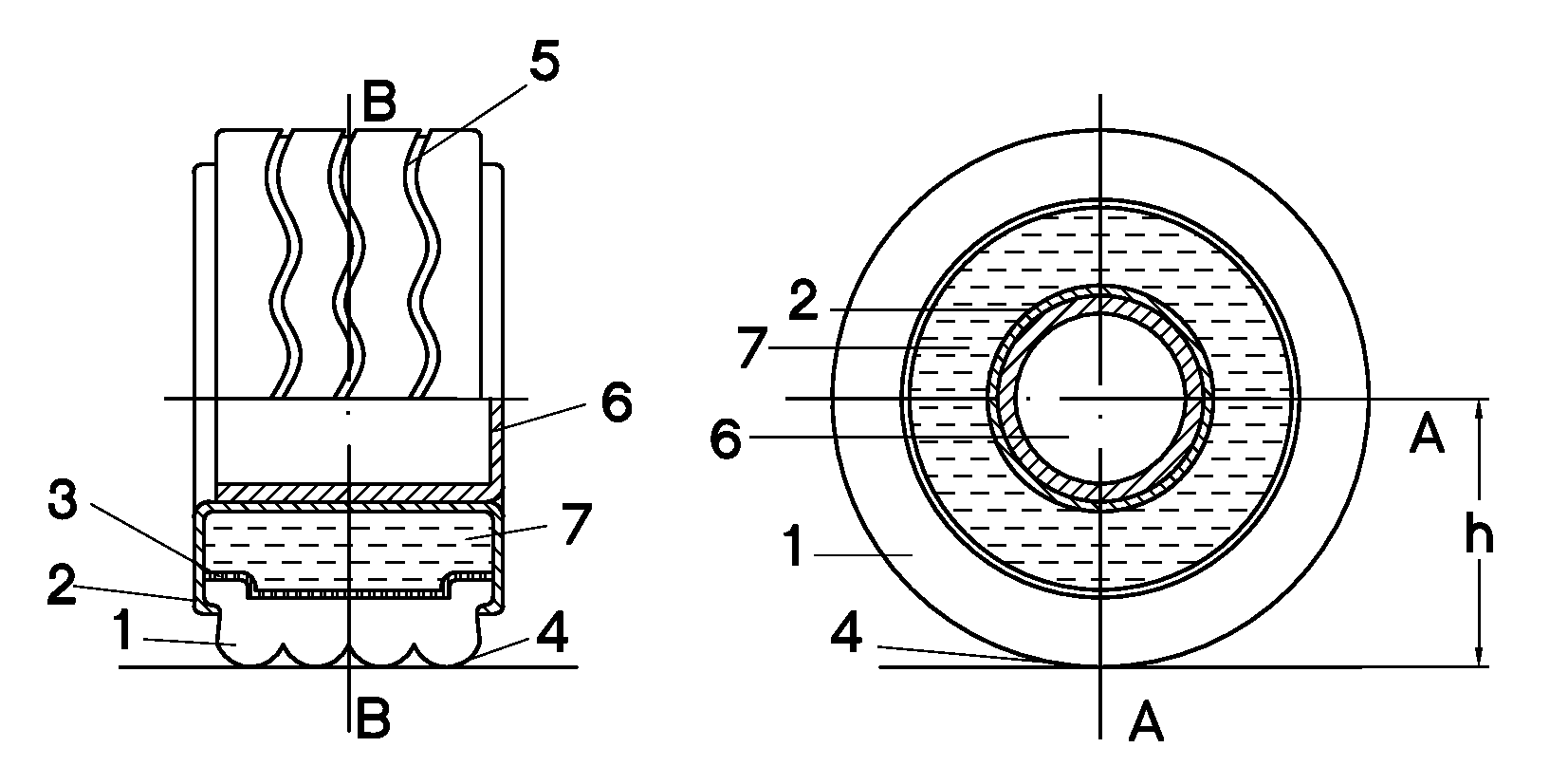
[0122]Referring to FIG. 1 and FIG. 2, the fluid-stuffed steel-tired wheel according to the preferred embodiment of the present invention is illustrated. The outer cover 1 and the steel ring 2 are detachably engaged by conventional means within the art. A plastic membrane 3 is overlappedly coated on the inner wall of the outer cover 1 so as to replace the conventional inner tube of a tire. It is noted that there is an engaging interface defined between the plastic membrane 3 and the inner wall of the outer cover 1. The landing portion 4 of the outer cover 1 is longitudinally flatted biasing the ground. Here, the landing portion refers to the circumferential surface of the outer cover 1 being contacted with the ground, so that a rotational motion of such wheel will enable turning part of the outer cover to land on the ground. The tire tread 5 is defined on the circumferential surface of outer cover 1. The steel ring 2 is coupled to the wheel rotational axial shaft through a steel basi...


PUM

PropertyMeasurementUnit
distanceaaaaaaaaaa
diameteraaaaaaaaaa
distanceaaaaaaaaaa

Abstract

The present invention discloses a type of secure and efficient wheel assembly using fluid or solid stuffing materials so as to minimize the blowout risks, a wheel rim transmission assembly, an energy exchanging arrangement used in transporting system, and a vehicle energy storage system, as well as corresponding methods for manufacturing and preparing such assemblies and arrangements in applications.

Description

CROSS REFERENCE TO THE RELATED PATENT APPLICATION[0001]The present application is a continuation application of the U.S. patent application Ser. No. 10 / 514,466 filed on Nov. 10, 2004 that is an US national stage of the PCT application No. PCT / CN03 / 00520 filed on Jul. 1, 2003, which claims the priorities of the Chinese patent applications No. 02126699.9 filed on Jul. 28, 2002, No. 02278550.7 filed on Jul. 30, 2002, No. 02278978.2 filed on Aug. 30, 2002 and No. 03116364.5 filed on Apr. 9, 2003, all applications are incorporated herein by reference.BACKGROUND OF THE PRESENT INVENTION[0002]1. Field of Invention[0003]The present invention relates to transporting system, more particularly, relates to a type of secure and efficient wheel assembly, a wheel rim transmission assembly, an energy exchanging arrangement used in transporting system, and a vehicle energy storage system, as well as corresponding methods for manufacturing and preparing such assemblies and arrangements in application...

Claims


Application Information

Patent Timeline
Patent Type & Authority Applications(United States)
IPC IPC(8): B60B19/00B29C73/16B60C5/10B60C5/00B60C5/02B60C7/00B60C19/12H02J7/00H02J15/00
CPCB60C5/007B60C5/02B60C17/04Y10T152/10036Y10T152/10675Y10T152/10495B60C17/06B60K2007/0061B60K7/0007B60K2007/0092
Inventor REN, WENLIN
Owner WUHAN RUNLIN SCI & TECH DEVMENT
Why Eureka
Try Eureka