Voltage sensing device

a voltage sensing and voltage technology, applied in the direction of ac/dc measuring bridges, reference comparisons, instruments, etc., can solve the problems of damage or fire, cell size may be too high, and time-consuming pre-shipment inspections

Active Publication Date: 2010-03-04
TEXAS INSTR INC
View PDF1 Cites 31 Cited by
  • Summary
  • Abstract
  • Description
  • Claims
  • Application Information

AI Technical Summary

Benefits of technology

[0012]In this aspect of the invention, the aforementioned first sensed signals generated by the aforementioned first sensed signal generating part include a fixed error, which is not dependent on the voltage at the aforementioned pair of sense input nodes, due to the effect of the input offset voltage etc. Th...

Problems solved by technology

During charging, for example, the voltage of some cells may be too high and cause problems, such as damage or fire.
However, this makes pre-shipment inspection time-consuming, and there is also the problem that the same operation is required when a device is to be replaced after shipment.
There is also the problem that increased errors due to temporal changes are unavoidable, since the same constant that was acquired at the time ...

Method used


Image

  • Voltage sensing device
  • Voltage sensing device
  • Voltage sensing device

Examples


first embodiment

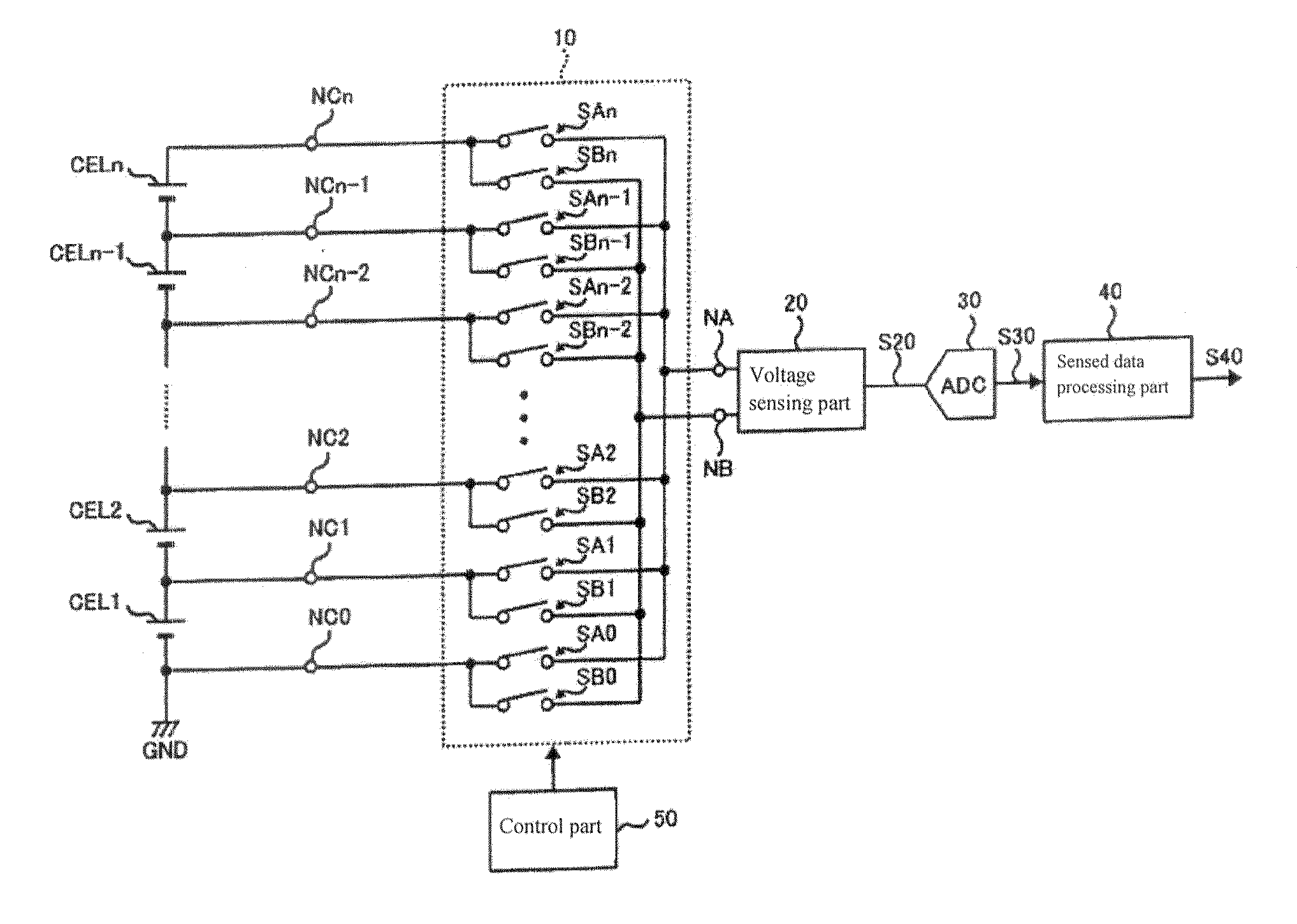
[0049]FIG. 1 shows an example of the configuration of a voltage sensing device pertaining to a first embodiment of the present invention.

[0050]The voltage sensing device shown in FIG. 1 is a device that senses the voltage of each cell of battery cells CEL1-CELn, which are connected in series, and has voltage input nodes NC0-NCn, a switch part 10, sense input nodes NA and NB, a voltage sensing part 20, an analog / digital conversion part 30, a sensed data processing part 40, and a control part 50. Switch part 10 has switches SA0-SAn and SB0-SBn.

[0051]Voltage input nodes NC0-NCn are one embodiment of the multiple voltage input nodes of the present invention. Sense input nodes NA and NB are one embodiment of the pair of sense input nodes of the present invention. Switch part 10 is one embodiment of the switch part of the present invention. Voltage sensing part 20 is one embodiment of the first sensed signal generating part of the present invention. Control part 50 is one embodiment of th...

second embodiment

[0093]A second embodiment of the present invention will now be explained.

[0094]The voltage sensing device pertaining to this embodiment is provided with an inspection mode relating to the switch part and to the input resistors. FIG. 6 shows an example of the configuration of a voltage sensing device pertaining to a second embodiment of the present invention.

[0095]In the voltage sensing device shown in FIG. 6, voltage sensing part 20 in the voltage sensing device shown in FIG. 1 is replaced with voltage sensing device 21, control part 50 is replaced with control part 51, and a judgment part 60 is also provided. The other symbols in FIG. 1 and FIG. 6 represent the same components.

[0096]Judgment part 60 is one possible embodiment of the first judgment part of the present invention.

[0097]FIG. 7 shows an example of the configuration of voltage sensing part 21.

[0098]Voltage sensing part 21 shown in FIG. 7, in addition to having the same configuration as voltage sensing part 20 shown in FI...

third embodiment

[0124]A third embodiment of the present invention will now be explained.

[0125]The voltage sensing device pertaining to this embodiment is provided with an inspection mode relating to the voltage sensing part.

[0126]FIG. 12 shows an example of the configuration of a voltage sensing device pertaining to a third embodiment. In the voltage sensing device shown in FIG. 12, switch part 10 in the voltage sensing device shown in FIG. 6 is replaced with a switch part 11, control part 51 is replaced with a control part 52, and inspection nodes NV0 and NV1 to which reference voltage Vref is input, a selection part 90, and a judgment part 70 are provided. The other symbols in FIG. 6 and FIG. 12 represent the same components.

[0127]Inspection nodes NV0 and NV1 are one possible embodiment of the pair of inspection nodes of the present invention. Judgment part 70 is one possible embodiment of the second judgment part of the present invention.

[0128]In switch part 11, inspection switches SVA0, SVA1, S...


PUM


Abstract

A voltage sensing device with which high-precision voltage sensing is possible without acquiring a unique correction constant for each device. A pair of voltage input nodes NCk and NCk-1 are selected from n+1 voltage input nodes NC0-NCn in switch part 10, and the selected voltage input nodes NCk and NCk-1 are connected to inspection input nodes NA and NB. Here, voltage input nodes NCk and NCk-1 and inspection input nodes NA and NB are connected in two types of patterns of different polarity (forward connection, reverse connection) under the control of control part 50, and digital data S30 for the two sensed voltage signals S20 generated in the two types of connection patterns is input to sensed data processing part 40. With sensed data processing part 40, sensed voltage data S40 that represents the potential difference between voltage input nodes NCk and NCk-1 is generated according to the difference in the two sensed voltage signals S20.

Description

CROSS-REFERENCE TO RELATED APPLICATIONS[0001]This patent application claims priority from Japanese Patent Application No. 2008-226501, filed 3 Sep. 2008, the entirety of which is incorporated herein by reference.TECHNICAL FIELD[0002]The present invention pertains to a voltage sensing device that senses the voltage applied between nodes that are at different electrical potentials relative to a reference potential; more specifically, it relates to a voltage sensing device that senses the voltage of each cell of a secondary battery that has a plurality of cells that are connected in series, for example.BACKGROUND OF THE INVENTION[0003]When a battery supplies energy to the drive system of a hybrid automobile or the like, generally, a voltage of around several hundred V is required; such batteries are often configured by connecting many secondary cells, such as lithium ion batteries, in series. When many secondary cells are connected in series, voltage variations occur because the charac...

Claims


Application Information

Patent Timeline
IPC IPC(8): G01R19/00
CPCG01R19/0084G01R31/3658G01R19/16542G01R31/396
Inventor TANAKA, TORUOGURA, AKIOOMAGARI, KAZUYAOGASAWARA, NARIAKI
Owner TEXAS INSTR INC
Why Eureka
Try Eureka