Unlock instant, AI-driven research and patent intelligence for your innovation.

Delay locked loop circuit

a loop circuit and delay technology, applied in the field of delay locked loop circuits, can solve the problems of unnecessarily consuming power, phase difference generation between external clocks and internal clocks, etc., and achieve the effect of reducing power consumption

Active Publication Date: 2010-03-04
SK HYNIX INC
View PDF17 Cites 23 Cited by
  • Summary
  • Abstract
  • Description
  • Claims
  • Application Information

AI Technical Summary

Benefits of technology

[0021]The present invention is proposed in order to overcome the above-described problems of conventional technologies. Embodiments of the present invention are directed to providing a delay locked loop circuit capable of reducing power consumption.

Problems solved by technology

However, since the external clock inputted to the semiconductor memory device is delayed by an internal circuit of the semiconductor memory device, a phase difference is generated between the external clock and an internal clock.
As a result, according to the conventional delay locked loop circuit, even when the second compensation unit 125 is not operated, the second delay locking unit 111 is still enabled, thereby unnecessarily consuming power after the completion of the duty ratio compensating operation.

Method used


Image

  • Delay locked loop circuit
  • Delay locked loop circuit
  • Delay locked loop circuit

Examples


Embodiment Construction

[0031]In order to describe in detail such that those skilled in the art easily implement the spirit and scope of the present invention, the embodiment of the present invention will be described with reference to the accompanying drawings.

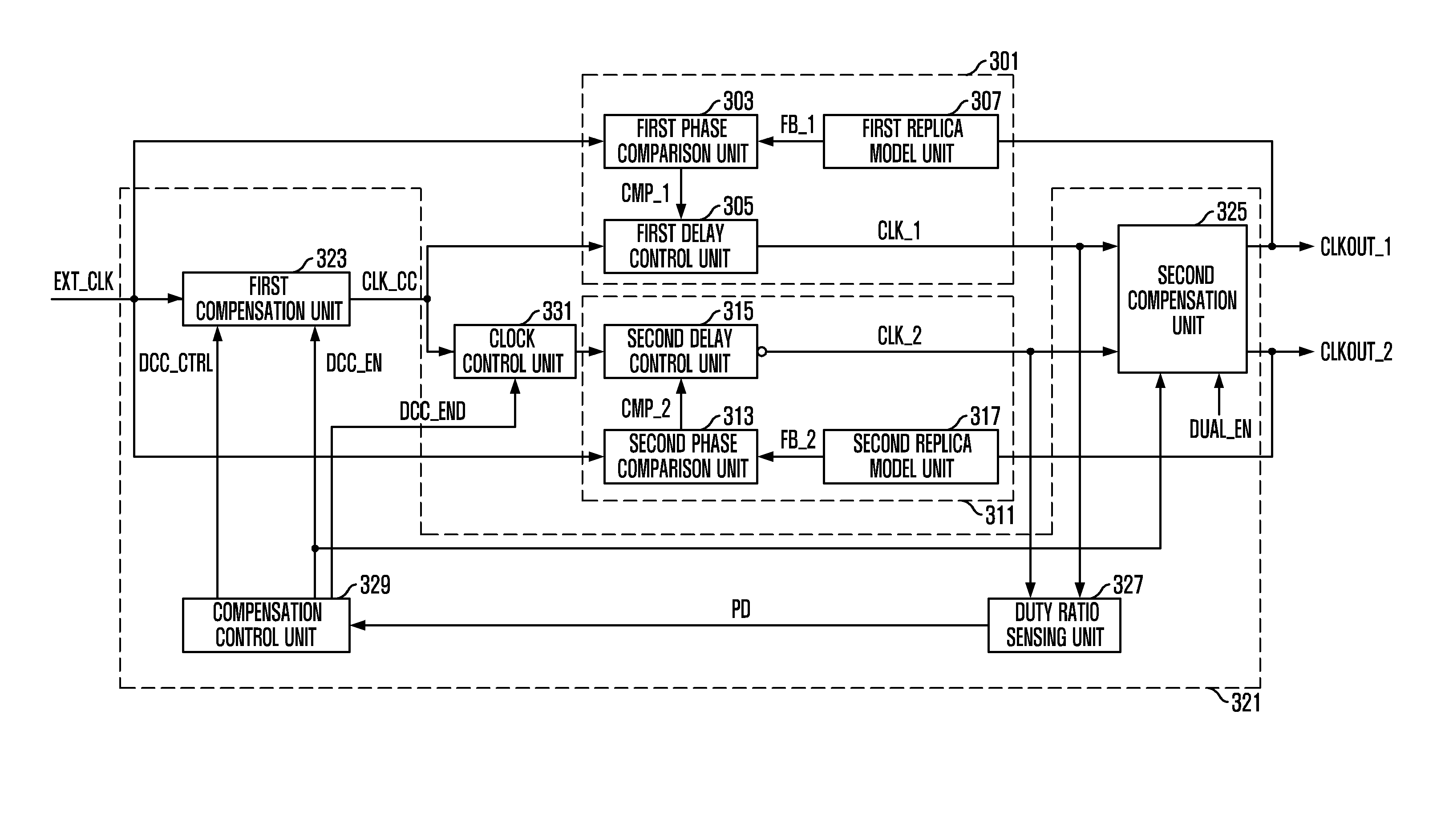
[0032]FIG. 3 is a block diagram depicting a delay locked loop circuit in accordance with an embodiment of the present invention.

[0033]As shown in the drawing, the delay locked loop circuit includes a first delay locking unit 301, a second delay locking unit 311, a duty ratio compensation unit 321 and a clock control unit 331.

[0034]Operations of the first and second delay locking units 301 and 311 and the duty ratio compensation unit 321 are similar to those of the first and second delay locking units 101 and 111 and the duty ratio compensation unit 121 of the conventional delay locked loop circuit. However, in case that a second compensation unit 325 is not operated due to deactivation of a dual compensation signal DUAL_EN, the duty ratio compensati...


PUM


Abstract

A delay locked loop circuit includes a delay locking unit configured to output a first internal clock and a second internal clock, a rising edge of which is synchronized with that of the first internal clock by delaying a compensated external clock for compensating a skew of a semiconductor memory device; a duty ratio compensation unit configured to generate the compensated external clock by compensating a duty ratio of an external clock of the semiconductor memory device and to compensate duty ratios of the first and second internal clocks; and a clock control unit configured to control an activation state of the second internal clock after the duty ratio compensation of the external clock.

Description

CROSS-REFERENCE TO RELATED APPLICATIONS[0001]The present invention claims priority of Korean patent application number 10-2008-0086109, filed on Sep. 2, 2008, which is incorporated by reference in its entirety.BACKGROUND OF THE INVENTION[0002]The present invention relates to a delay locked loop circuit, and more particularly, to a delay locked loop circuit capable of reducing power consumption.[0003]Generally, a Delay Locked Loop (DLL) circuit controls a timing of data outputted from a memory device, e.g., a synchronous semiconductor memory device, by using an external clock inputted from the outside of the memory device.[0004]In order to transfer the output data of the semiconductor memory device to a chip set without an error, the semiconductor memory device and the chip set should be synchronized with the external clock. However, since the external clock inputted to the semiconductor memory device is delayed by an internal circuit of the semiconductor memory device, a phase diffe...

Claims


Application Information

Patent Timeline
IPC IPC(8): H03L7/06
CPCH03L7/087H03L7/0812H03L7/0814H03L7/0816G11C7/22G11C2207/2227H03K5/1565
Inventor CHUNG, JIN-ILCHOI, HOON
Owner SK HYNIX INC
Features
  • R&D
  • Intellectual Property
  • Life Sciences
  • Materials
  • Tech Scout
  • Unparalleled Data Quality
  • Higher Quality Content
  • 60% Fewer Hallucinations
Learn More