Eureka AIR delivers breakthrough ideas for toughest innovation challenges, trusted by R&D personnel around the world.

Pulse width modulation device

Inactive Publication Date: 2010-03-04
KK TOSHIBA
View PDF2 Cites 4 Cited by
  • Summary
  • Abstract
  • Description
  • Claims
  • Application Information

AI Technical Summary

Benefits of technology

[0014]an edge detection device that inputs the aforementioned comparison signal and top/bottom signal and is provided with an edge detection function that generates and outputs an edge detection signal by detecting change of the comparison signal and wherein the edge detection signal inhibits the edge detection function and the top/bottom signal cancels inhibition of the edge detection function; and
[0015]a pulse generating device that outputs a pulse width modulation signal obtained by pulse width modulation of the control signal by the carrier signal in accordance with the aforementioned comparison signal, edge detection signal and top/down signal.
[0016]The edge detection device

Problems solved by technology

In a first PWM device of this type, when the amount of change of the control signal is large, the phenomenon of excessive generation of pulses of narrow width occurs.
For example, if the control signal is of step form waveform (i.e. a square wave), when the control signal changes in stepwise fashion immediately after coincidence of the control signal and the triangular wave carrier signal, excessive generation of pulses of narrow width occurs due to the control signal again coinciding with the triangular wave carrier signal, resulting in the inconvenience of production of distortion in the PWM signal due to these excess pulses.
However, in the case of the second conventional PWM device described in Published Japanese Patent 3486914referred to above, an up / down signal generating device and a coincidence device are necessary, and the first conventional PWM device cannot be utilized without modification.
The circuit construction therefore became complicated or, in cases where for example it was necessary to generate pulses in addition to the second pulse, there was the problem of inconvenience in that it was not possible to adopt the countermeasure of generating a PWM signal by for example software control in which this function was disabled.

Method used


Image

  • Pulse width modulation device
  • Pulse width modulation device
  • Pulse width modulation device

Examples


first embodiment

[0023]An embodiment of the present invention is described below with reference to the drawings.

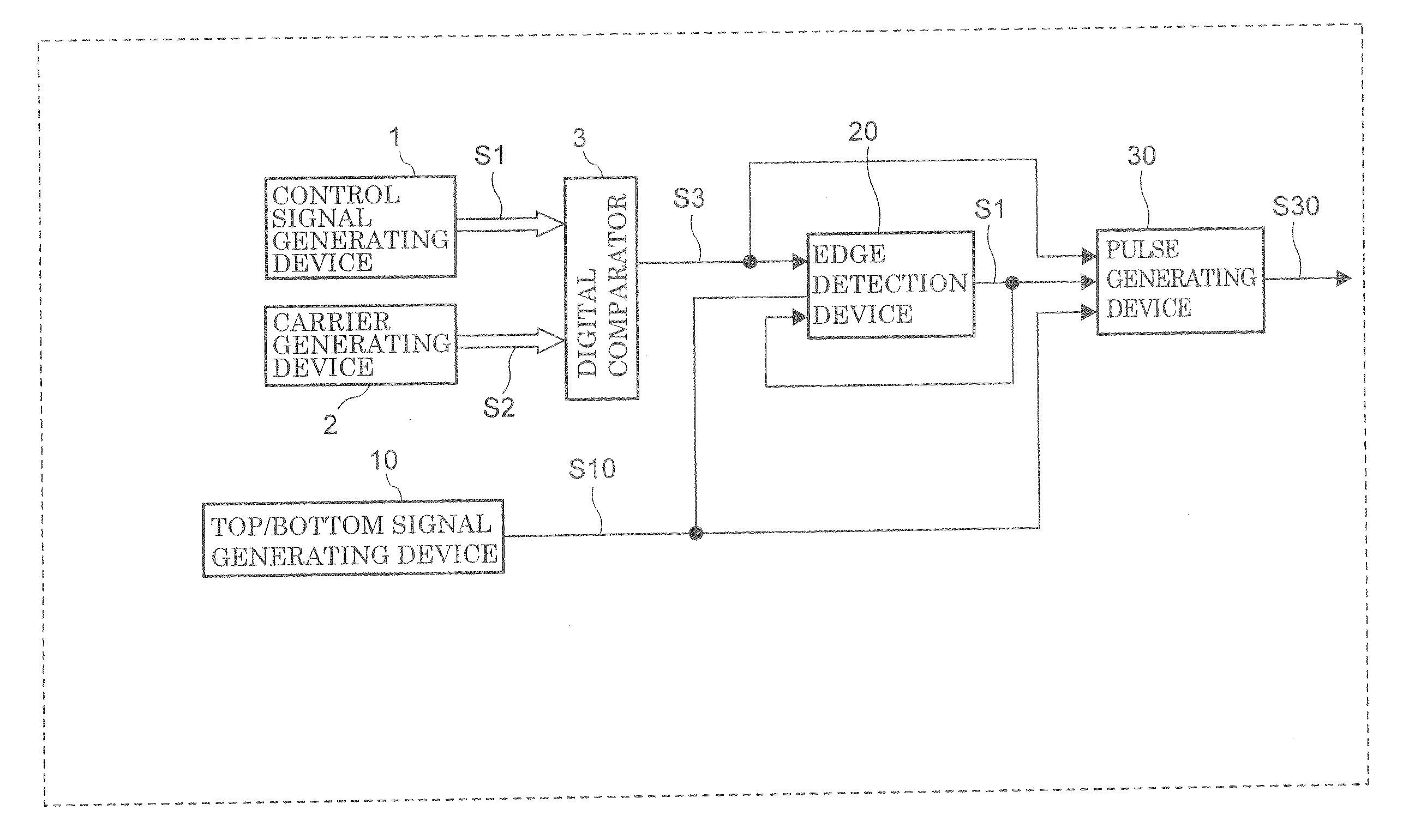
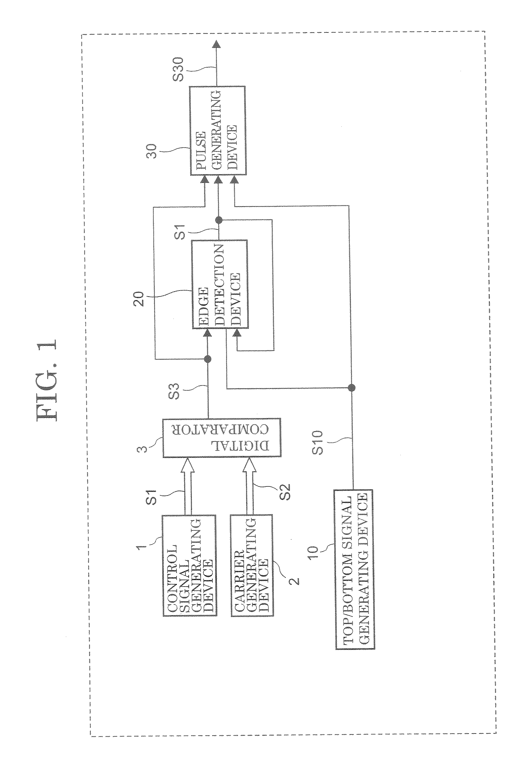
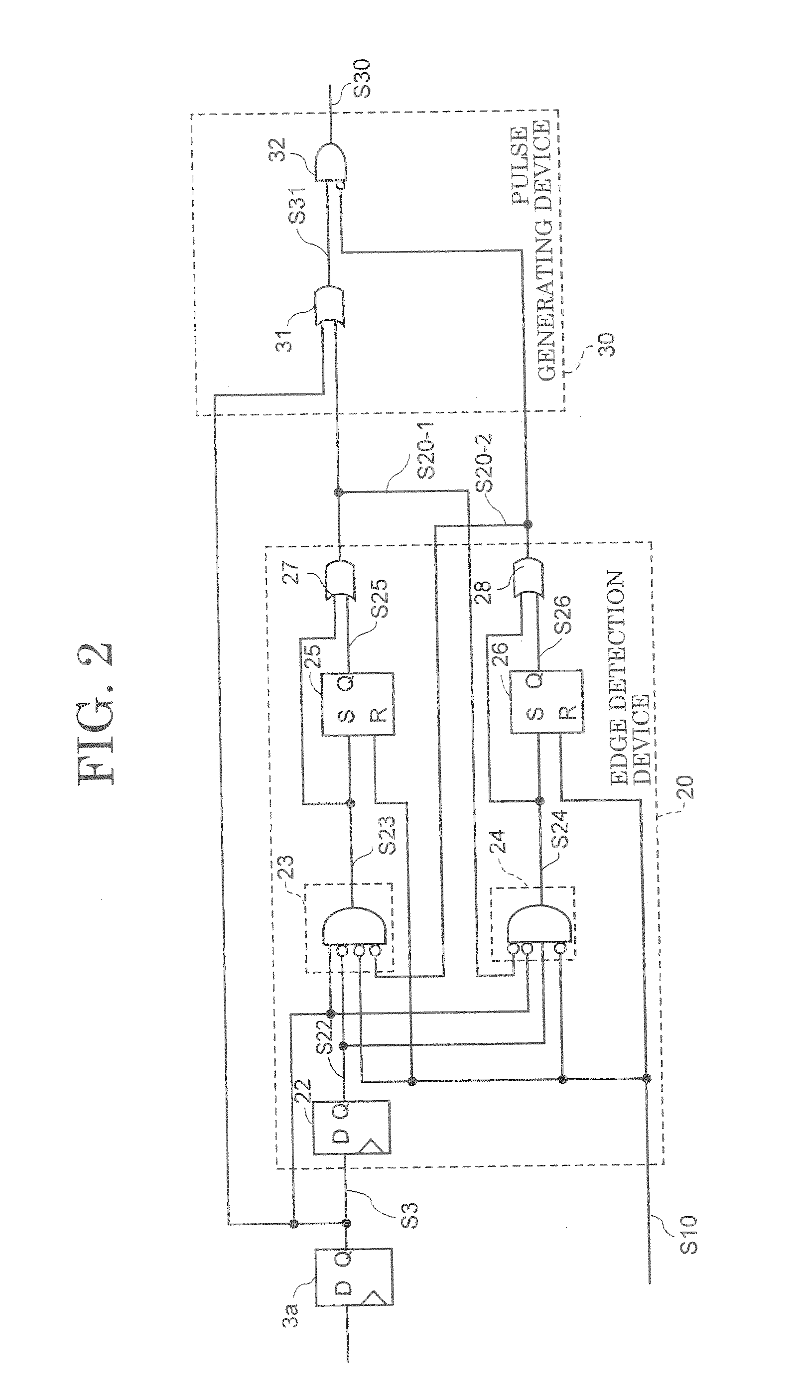
[0024]A PWM device comprises: a control signal generating device that generates a step form control signal; a carrier generating device that generates a triangular wave carrier signal for pulse width modulation of the control signal; a digital comparator that outputs a comparison signal as a result of comparison of the control signal and the carrier signal; a top / bottom signal generating device that generates a top / bottom signal when the carrier signal reaches the top or bottom of the triangular wave; an edge detection device; and a pulse generating device.

[0025]The aforementioned edge detection device comprises an edge detection function whereby a comparison signal and top / bottom signal are input, and an edge detection signal is generated by detecting change of the comparison signal. The edge detection signal inhibits the edge detection function but the top / bottom signal cancels inhibitio...

second embodiment

Construction of the Second Embodiment

[0054]FIG. 5 is a constructional diagram of a PWM device illustrating a second embodiment of the present invention. Elements that are the same as elements in FIG. 1 illustrating the first embodiment are given the same reference symbols.

[0055]In the PWM device according to the second embodiment of the present invention, a construction is adopted wherein it is possible to select the pulse control function, by adding to the PWM device of the first embodiment a flag 41 for selection of the pulse control function, and changing over a selection device (for example, selector) 42 in response to the output signal S41 of this flag 41.

[0056]The flag 41 is constituted for example by a register whereby the pulse control function is set to be active or inactive, the construction being such that the pulse control function can be selected to be active or inactive by setting this register to “1” or resetting this to “0” under the control of an instruction from fo...


PUM


Abstract

A pulse width modulation device in which a step form control signal generated by a control signal generating device and a triangular wave carrier signal generated by a carrier generating device are compared by a digital comparator and the comparison signal is supplied to an edge detection device. Also, a top / bottom signal generated by a top / bottom signal generating device is supplied to the edge detection device The edge detection device includes an edge detection function that generates an edge detection signal by detecting change of the comparison signal. The edge detection function is inhibited by the edge detection signal; and inhibition is cancelled by the top / bottom signal so that the edge detection signal is output. A PWM signal is output from the pulse generating device in accordance with the comparison signal, edge detection signal, and top / bottom signal.

Description

TECHNICAL FIELD[0001]The present invention relates to a pulse width modulation (hereinbelow turned “PWM”) device that performs pulse width modulation of a control signal by a carrier wave signal.BACKGROUND ART[0002]An example of a reference regarding a PWM device is Published Japanese Patent No. 3486914 (Laid-open Japanese Patent Application No. H. 6-188702).[0003]In a previously known PWM device (hereinbelow this device is termed a “first PWM device”), a PWM signal is generated by using a digital comparator to compare the magnitudes of a control signal generated by a control signal generating device and a triangular wave carrier signal generated by a carrier generating device.[0004]In a first PWM device of this type, when the amount of change of the control signal is large, the phenomenon of excessive generation of pulses of narrow width occurs. For example, if the control signal is of step form waveform (i.e. a square wave), when the control signal changes in stepwise fashion imme...

Claims


Application Information

Patent Timeline
IPC IPC(8): H03K7/08
CPCH03K7/08
Inventor YANG, CHONGSHANOZAKI, HIROSHITANAKA, HIROYUKI
Owner KK TOSHIBA
Why Eureka
Eureka Blog
Learn More