
Ultra-high Density Diffraction Grating

a diffraction grating, ultra-high density technology, applied in the direction of optical radiation measurement, instruments, spectrometry/spectrophotometry/monochromators, etc., can solve the problems affecting the development of such gratings, and achieve the effect of improving the resolution of spectroscopic instruments

Inactive Publication Date: 2010-03-04
RGT UNIV OF CALIFORNIA
View PDF2 Cites 25 Cited by
  • Summary
  • Abstract
  • Description
  • Claims
  • Application Information

AI Technical Summary

Benefits of technology

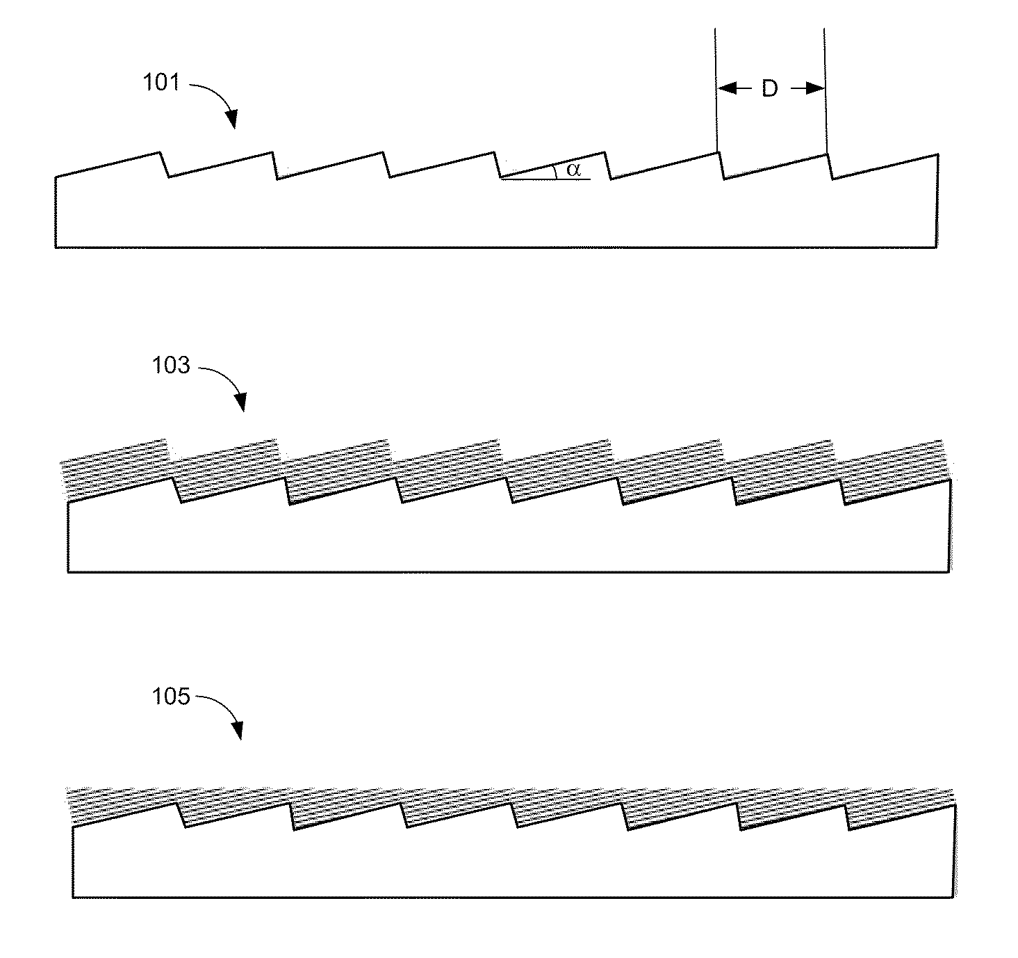
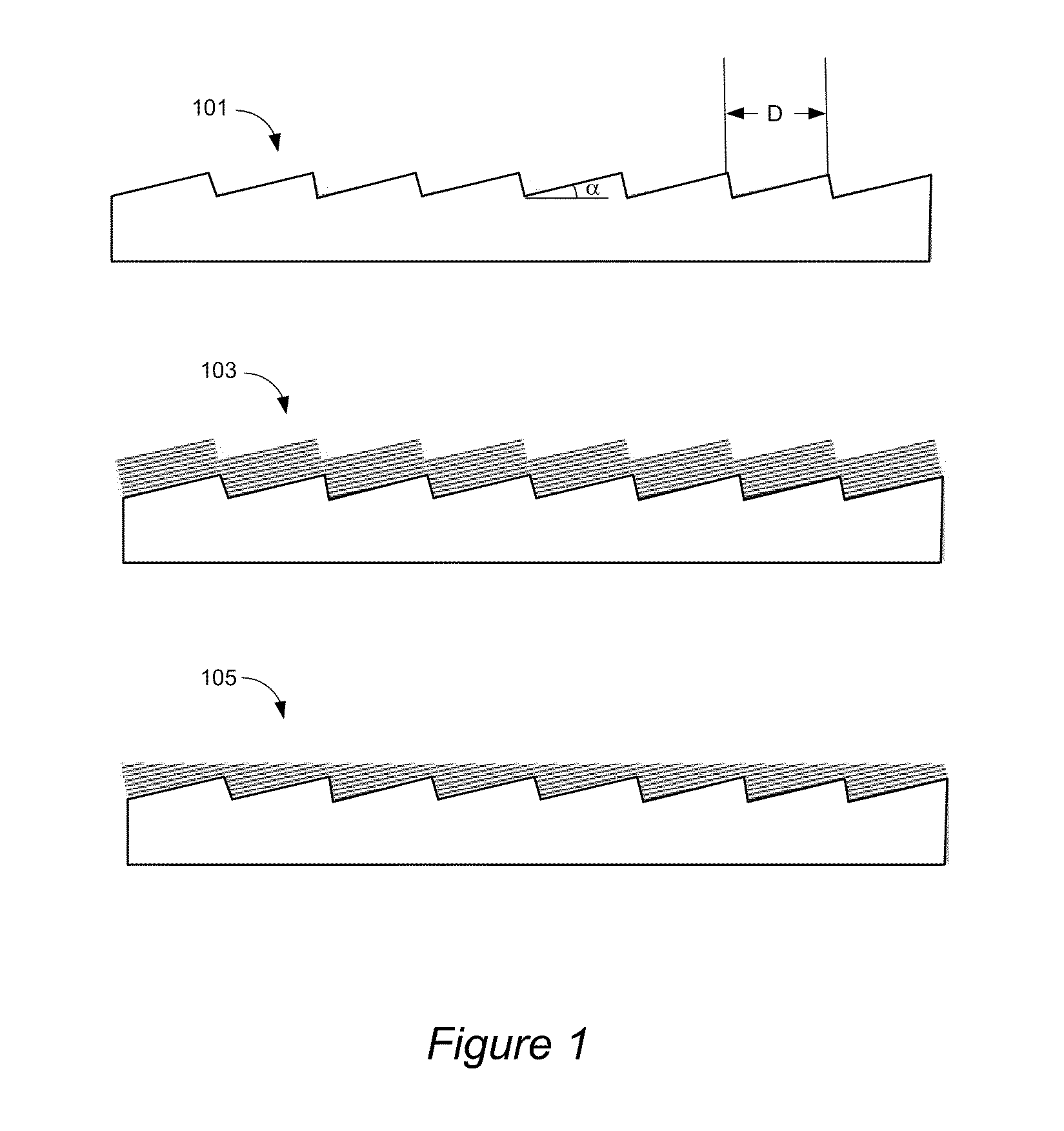
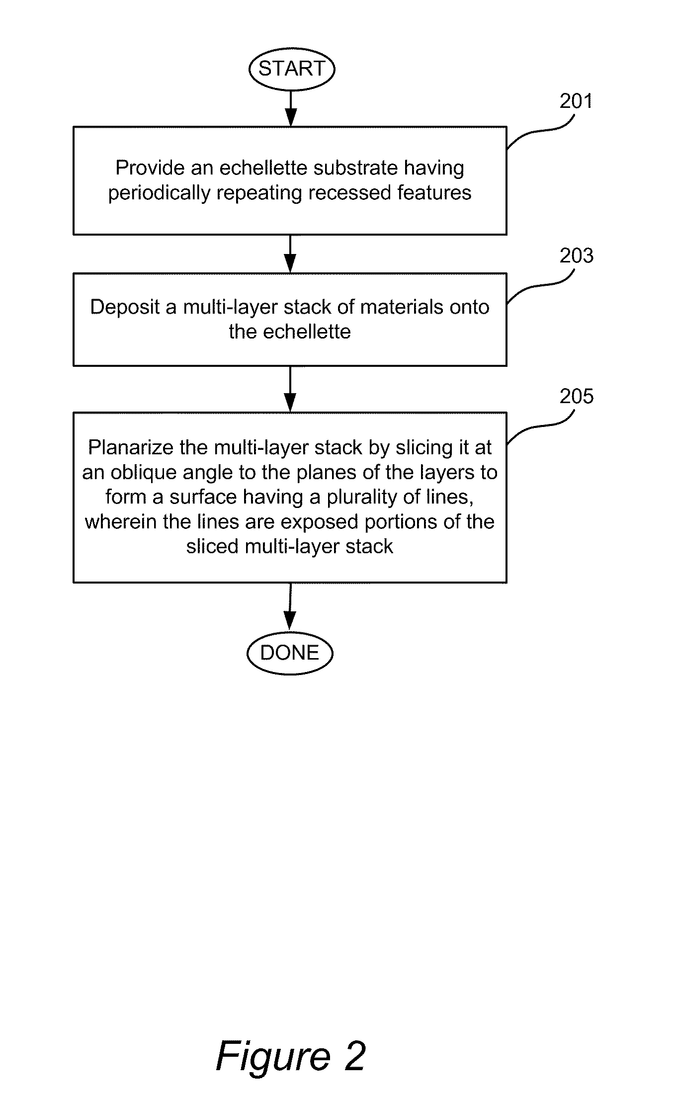
This patent describes an ultra-high density diffraction grating structure that can be used in a variety of spectroscopic instruments. The grating has a line density of between 10,000 and 100,000 lines per millimeter, which significantly improves the resolution of these instruments. The grating is made up of an echellette substrate with periodically repeating recessed features and a multi-layer stack of materials that have alternating properties. The lines are planarized and aligned in a straight manner. The grating can be used in a RIXS spectrometer and is made using a variety of methods such as physical vapor deposition, chemical vapor deposition, atomic layer deposition, and chemical mechanical polishing. The ultra-high density of lines allows for improved performance of the spectroscopic instruments.

Problems solved by technology

Fabrication of suitable ultra-high density grating structures, however, presents a number of challenges that impede the development of such gratings.

Method used


Image

  • Ultra-high Density Diffraction Grating
  • Ultra-high Density Diffraction Grating
  • Ultra-high Density Diffraction Grating

Examples


Embodiment Construction

[0015]In the following description, the invention is presented in terms of certain specific structures, configurations, and processes to help explain how it may be practiced. The invention is not limited to these specific embodiments. Examples of specific embodiments of the invention are illustrated in the accompanying drawings. While the invention will be described in conjunction with these specific embodiments, it will be understood that it is not intended to limit the invention to such specific embodiments. On the contrary, it is intended to cover alternatives, modifications, and equivalents as may be included within the scope and equivalents of the appended claims. In the following description, numerous specific details are set forth in order to provide a thorough understanding of the present invention. The present invention may be practiced without some or all of these specific details. In other instances, well known process operations have not been described in detail in order...


PUM

PropertyMeasurementUnit
lengthsaaaaaaaaaa
energy resolutionaaaaaaaaaa
lengthaaaaaaaaaa

Abstract

A diffraction grating structure having ultra-high density of grooves comprises an echellette substrate having periodically repeating recessed features, and a multi-layer stack of materials disposed on the echellette substrate. The surface of the diffraction grating is planarized, such that layers of the multi-layer stack form a plurality of lines disposed on the planarized surface of the structure in a periodical fashion, wherein lines having a first property alternate with lines having a dissimilar property on the surface of the substrate. For example, in one embodiment, lines comprising high-Z and low-Z materials alternate on the planarized surface providing a structure that is suitable as a diffraction grating for EUV and soft X-rays. In some embodiments, line density of between about 10,000 lines / mm to about 100,000 lines / mm is provided.

Description

CROSS-REFERENCE TO RELATED APPLICATIONS[0001]This application claims benefit of prior U.S. Provisional Application No. 61 / 084,551 filed Jul. 29, 2008, titled “Ultra-high Density Diffraction Grating” naming Padmore et al. as inventors, which is herein incorporated by reference in its entirety and for all purposes.STATEMENT OF GOVERNMENTAL SUPPORT[0002]This invention was made with government support under Contract No. DE-AC02-05CH11231 awarded by the United States Department of Energy. The government has certain rights in the invention.FIELD OF THE INVENTION[0003]The invention relates to diffraction grating structures and methods of their fabrication. More specifically, the invention relates to ultra-high density diffraction grating structures suitable for diffraction of EUV and soft X-rays in spectroscopic applications.BACKGROUND OF THE INVENTION[0004]Development of high resolution diffraction gratings for the EUV and soft X-ray energy ranges is an area of interest both in modern ast...

Claims


Application Information

Patent Timeline
Patent Type & Authority Applications(United States)
IPC IPC(8): G01J3/18B29D11/00C23C14/00C23C14/34B05D5/06C23C14/35G02B5/18
CPCB29D11/0073B29D11/00769B82Y10/00G01J3/1809G21K2201/067G21K1/06G21K1/062G21K2201/061G02B5/1838
Inventor PADMORE, HOWARD A.VORONOV, DMYTRO L.CAMBIE, ROSSANAYASHCHUK, VALERIY V.GULLIKSON, ERIC M.
Owner RGT UNIV OF CALIFORNIA
Learn More