Printing system, control method, and storage medium

a printing system and control method technology, applied in the direction of printing units, instruments, visual presentations using printers, etc., can solve the problems of no effective proposal seen, printing is temporarily stopped, and a lot to be studied, so as to improve the productivity of post-processing units, improve productivity, and flexiblely execute post-processing effects

Inactive Publication Date: 2010-03-04
CANON KK
View PDF6 Cites 21 Cited by
  • Summary
  • Abstract
  • Description
  • Claims
  • Application Information

AI Technical Summary

Benefits of technology

[0011]According to the present invention, post processing by the post-processing unit connected to the printing unit can be used without involving printing by the printing unit. This makes it possible to execute only post processing that can be executed by the post-processing unit in a manner separate from a printing job. Therefore, it is possible to improve the productivity of the post-processing unit connected to the printing unit. Further, according to the present invention, when the printing job is stopped due to a cause which does not hinder execution of post processing, it is possible to execute the post processing by the post-processing unit. This makes it possible to flexibly execute the post processing instructed by the user, to thereby improve productivity.

Problems solved by technology

However, there is still a lot to be studied before such a POD printing system is made commercially available i.e. put into practical use.
However, since such a demand is not strong in actuality, no effective proposal has ever been seen.
Further, during printing by the printing system, it sometimes occurs that the printing is temporarily stopped due to some cause (maintenance of the printer, running out of toner, paper jam, etc.).
During the stop of the printing, the printing system cannot operate, which causes lowering of the productivity of the printing system.

Method used


Image

  • Printing system, control method, and storage medium
  • Printing system, control method, and storage medium
  • Printing system, control method, and storage medium

Examples


Embodiment Construction

[0027]The present invention will now be described in detail below with reference to the accompanying drawings showing embodiments thereof. However, description of the following embodiments is given only by way of example, and it is to be construed that examples disclosed therein are to be modified as required according to the configuration of an apparatus to which the present invention is applied, and other various conditions, but the present invention is by no means limited to them.

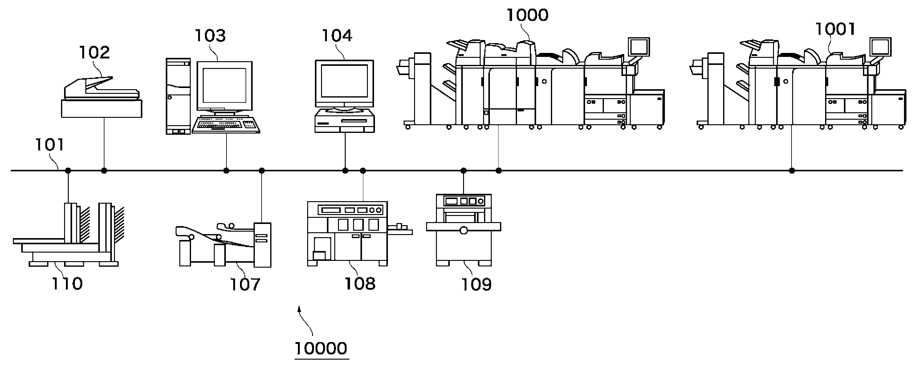
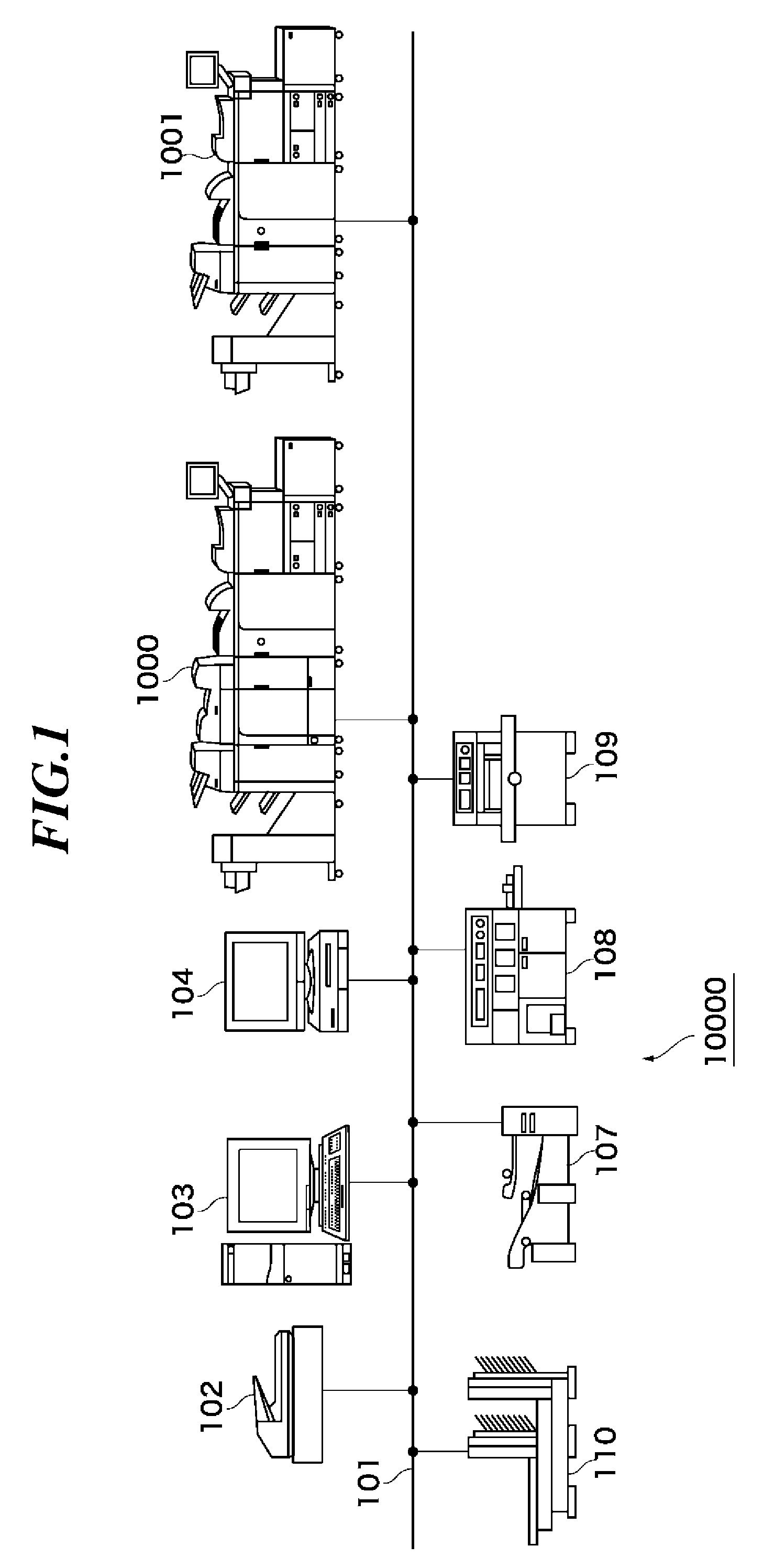
[0028]A POD system 10000 shown in FIG. 1 includes printing systems 1000 and 1001, a scanner 102, a server computer 103 (hereinafter referred to as “the PC 103”), and a client computer 104 (hereinafter referred to as “the PC 104”), which are interconnected via a network 101. Further, the POD system 10000 includes a sheet folding machine 107, a cutting machine 109, a saddle stitching machine 110, and a case binding machine 108.

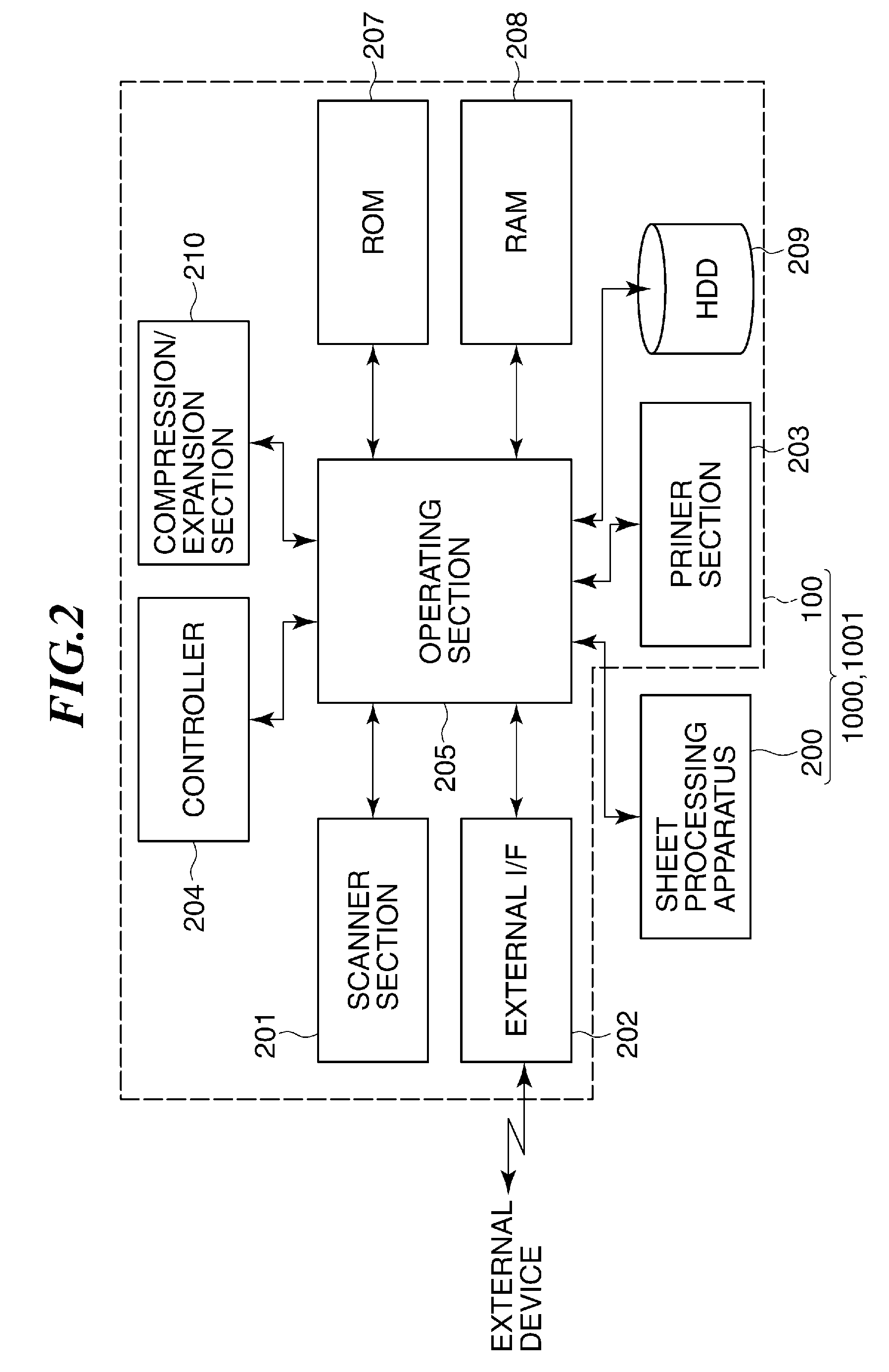
[0029]Referring to FIG. 2, each of the printing system 1000 and 1001 is comprise...


PUM


Abstract

A printing system that conveys sheets printed by a printing unit to a sheet processing unit connected to the printing unit and causes the sheet processing unit to perform post processing on the sheet. When an inline job is temporarily stopped in which sheets printed by the printing unit are conveyed to the post-processing unit, and post processing is caused to be executed on the sheets by the post-processing unit, if an offline job is executable in which sheets are fed from a predetermined sheet feed section without executing printing by the printing unit, and post processing is caused to be executed on the sheets by the post-processing unit, the offline job is permitted to be executed.

Description

BACKGROUND OF THE INVENTION[0001]1. Field of the Invention[0002]The present invention relates to a printing system, a control method, and a storage medium storing a program for causing a computer to execute the control method, which enable a post-processing unit connected to a printing unit to execute only post processing without involving printing by the printing unit.[0003]2. Description of the Related Art[0004]Recently, a POD (Print On Demand) printing system using an electrophotographic printing apparatus or an inkjet printing apparatus has been proposed so as to outdo the conventional printing industry (see e.g. US Published Application No. 20040190057). The POD printing system of this type makes it possible to dispense with an operation for preparing a final copy for printing and other complicated operations.[0005]However, there is still a lot to be studied before such a POD printing system is made commercially available i.e. put into practical use. For example, the convention...

Claims


Application Information

Patent Timeline
Patent Type & Authority Applications(United States)
IPC IPC(8): G06F15/00
CPCB41J13/0009G06F3/1264G06F3/121G03G15/50G06K15/16G06K15/408
Inventor SATO, MASAYUKI
Owner CANON KK
Why Eureka
Try Eureka