
Parallel-connected uninterrupted power supply circuit

a power supply circuit and parallel connection technology, applied in emergency power supply arrangements, climate sustainability, energy industry, etc., can solve problems such as current imbalance, large emi, and out of control status, so as to reduce the use of magnetic elements, reduce the volume of ups power mode, and reduce the effect of emi

Active Publication Date: 2010-03-04
DELTA ELECTRONICS INC
View PDF4 Cites 44 Cited by
  • Summary
  • Abstract
  • Description
  • Claims
  • Application Information

AI Technical Summary

Benefits of technology

[0008]It is therefore an object of the present invention to provide a parallel-connected UPS circuit, and this circuit realizes the multiple UPS modes parallel-connected to a battery set, causes all the UPS modes to reach a current balance and reduces the usage of magnetic elements while comparing to the conventional configuration thus to dramatically decrease the volume of the UPS power mode, greatly diminish the EMI, relatively decrease the manufacturing costs and the total costs of the parallel-connected UPS circuit at the same time due to that an inductor is decreased and a switch is increased in each of the UPS modes.
[0021]Preferably, the circuit operates under one of a DC mode having a positive and a negative half-cycles and an AC mode having a positive and a negative half-cycles, wherein each of the first and the second control switches is an IGBT having a reverse parallel-connected diode, the first and the second control switches are turned on while under the positive half-cycle of the DC mode and the positive and the negative half-cycle of the AC mode; the first and the second control switches are turned off while under the negative half-cycle of the DC mode where the reverse parallel-connected diodes of the first and the second control switches are respectively used to prevent reverse flows of a first current of the first control switch and a second current of the second control switch and to bear a first reverse and a second reverse voltages such that the first and the second PFC circuits reach a current balance at this time moment.
[0028]Preferably, the circuit operates under one of a DC mode having a positive and a negative half-cycles and an AC mode having a positive and a negative half-cycles, wherein the control switch is an IGBT having a reverse parallel-connected diode, the control switch is turned on while under the positive half-cycle of one of the DC mode and the positive and the negative half-cycle of AC mode, and the control switch is turned off while under the negative half-cycle of the DC mode where the reverse parallel-connected diode of the control switch is used to prevent a reverse flow of a current of the control switch and to bear a reverse voltage such that all the PFC circuits reach a current balance at this time moment.

Problems solved by technology

Due to that the positive and the negative terminals of the battery are connected to the neutral through the inductors L1 and L2 when the above-mentioned conventional online UPS is in a battery mode, thus the voltage on the neutral generates a voltage jump while switching and results in a quite large EMI.
But this kind of conventional configuration of the UPS can not realize multiple parallel-connected UPSs with a jointly used battery set, and a jointly used neutral would result in a current unbalance of the two UPS modes and cause an out of control status after the multiple UPSs, each of which is shown in FIG. 1, are parallel-connected.
Furthermore, the magnetic elements such as the inductors are manufactured by mine materials containing copper and iron, and the costs of which are increasingly higher following the development of the economy.
In this way, the currents flow through the inductors of each UPS mode are hardly to be independently controlled, which causes the input power of each UPS to be different from each other, result in inductor current oscillations and the current unbalance of switches, and the single battery set parallel-connected to multiple UPSs can not be realized also.

Method used


Image

  • Parallel-connected uninterrupted power supply circuit
  • Parallel-connected uninterrupted power supply circuit
  • Parallel-connected uninterrupted power supply circuit

Examples


Embodiment Construction

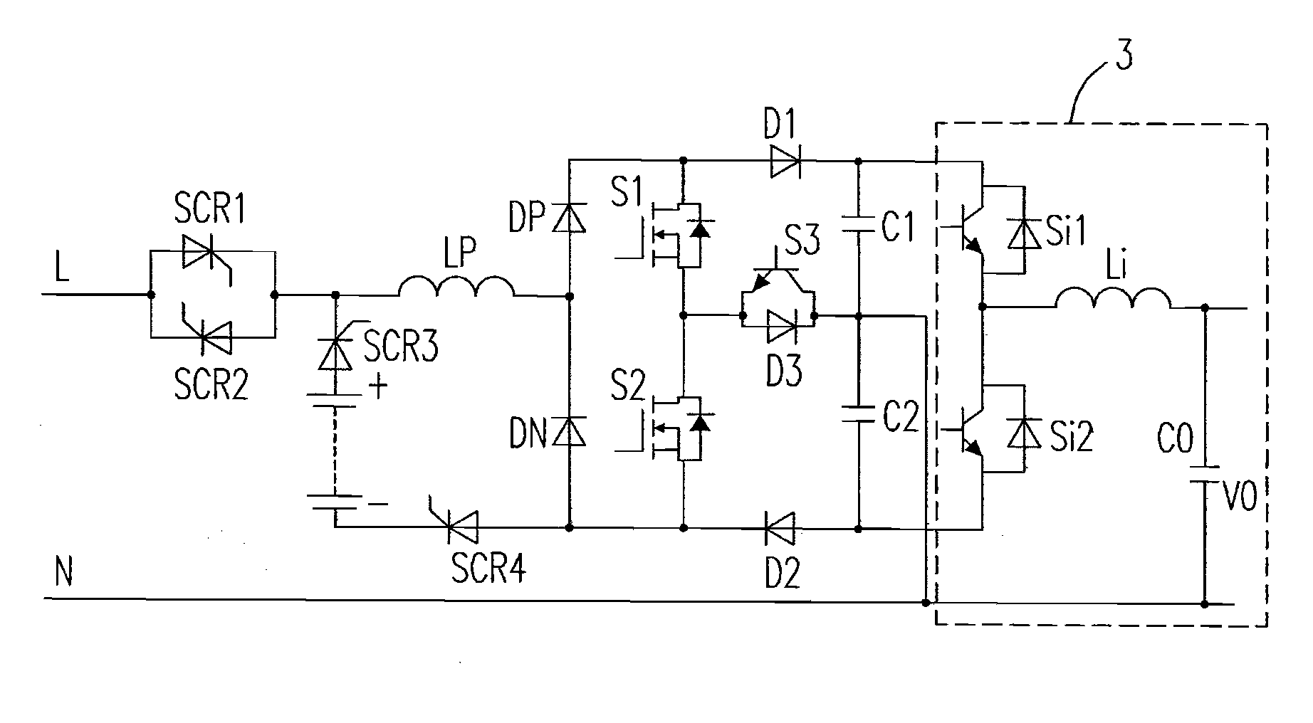
[0042]Please refer to FIG. 3, it shows a circuit diagram of an online UPS according to the first preferred embodiment of the present invention. In FIG. 3, there is only an inductor Lp used for the PFC and connected before the rectifying bridge of DP and DN, and after the battery. In the AC mode, this inductor Lp is used to engage the conversion no matter it is in the positive half-cycle or the negative half-cycle of the input voltage. The UPS enters the DC (battery) mode when the AC is cut off, and the positive terminal of the battery set goes through a SCR SCR3 and connects to the front-end of PFC inductor Lp. In the DC mode, the AC switch is turned off, and the battery set goes through the jointly used PFC circuit to transfer the energy to the positive / negative terminals of the DC bus for providing the power to the inverter 3. The negative terminal of the battery set goes through a SCR SCR4 to be connected to the lower switch S2 of the PFC circuit.

[0043]To realize a parallel opera...


PUM


Abstract

The configurations of a parallel-connected UPS circuit are provided in the present invention. The proposed circuit includes a neutral, a battery having a positive and a negative terminals, and a plurality of PFC boost converters, each of which includes a PFC circuit including an inductor having a first terminal coupled to the positive terminal and a second terminal, a rectifying bridge coupled to the second terminal of the inductor, and having a first terminal and a second terminal coupled to the negative terminal, a switch bridge having a first terminal coupled to the first terminal of the rectifying bridge and a second terminal coupled to the second terminal of the rectifying bridge, and a control switch having a first terminal and a second terminal coupled to the neutral.

Description

FIELD OF THE INVENTION[0001]The present invention relates to a parallel-connected uninterrupted power supply (UPS) circuit. More particularly, it relates to a circuit having a plurality of UPSs parallel-connected to each other such that the plurality of UPSs could reach a current balance.BACKGROUND OF THE INVENTION[0002]The UPS is applied in the power supply of the critical equipment. In FIG. 1, it shows a circuit diagram of a conventional online UPS. In which, it includes a power factor correction (PFC) boost converter (including silicon-controlled rectifiers (SCRs) SCR1-SCR2, inductors L1-L2, switches S1-S2, diodes D1-D2 and capacitors C1-C2), an inverter (including switches Si1-Si2, inductor Li and output capacitor Co), a controller (not shown) and a battery set (including a battery having a positive terminal and a negative terminal, SCRs SCR3-SCR4 and a fuse F2), and it further includes an input electrical magnetic interference (EMI) filter having a bypass AC input terminal, a n...

Claims


Application Information

Patent Timeline
Patent Type & Authority Applications(United States)
IPC IPC(8): H02M5/45
CPCH02J2009/063H02J9/062H02J9/063Y02P80/10
Inventor LU, YANSONGTAN, JINGTAOCHEN, XIAOYU, HAOYING, JIANPING
Owner DELTA ELECTRONICS INC
Features
  • Generate Ideas
  • Intellectual Property
  • Life Sciences
  • Materials
  • Tech Scout
  • Unparalleled Data Quality
  • Higher Quality Content
  • 60% Fewer Hallucinations
Learn More