Communication Method, Communication System, Communication Terminal Apparatus and Base Station Apparatus

a communication system and base station technology, applied in the field of communication systems, can solve the problems of inefficiency in power management to shift to and recover from a power saving mode, waste of standby power, etc., and achieve the effects of preventing the delay of data transmission reducing the burden of data holding in the base station apparatus, and stable service quality

Inactive Publication Date: 2010-03-04
KYOCERA CORP
View PDF11 Cites 10 Cited by
  • Summary
  • Abstract
  • Description
  • Claims
  • Application Information

AI Technical Summary

Benefits of technology

[0054]According to the present invention, the burden of data holding in the base station apparatus can be reduced during communication with a plurality of sessions, and thus it is possible to prevent delay of data transmission in the base station apparatus. Moreover, since it enables realtime communication of data of the prioritized service type, stable service quality can be maintained in realtime communication.

Problems solved by technology

In the case of controlling power supply in a relay apparatus having a plurality of interfaces, although a wired interface (IEEE (Institute Electrical and Electronics Engineers) 1394) and a wireless interface of the relay apparatus of the conventional art have a wired standby means and a wireless standby means respectively, there is no comprehensive power control method and thus controlling the power supply may cause waste of standby power and inefficiency in power management to shift to and recovery from a power save mode.

Method used


Image

  • Communication Method, Communication System, Communication Terminal Apparatus and Base Station Apparatus
  • Communication Method, Communication System, Communication Terminal Apparatus and Base Station Apparatus
  • Communication Method, Communication System, Communication Terminal Apparatus and Base Station Apparatus

Examples


first embodiment

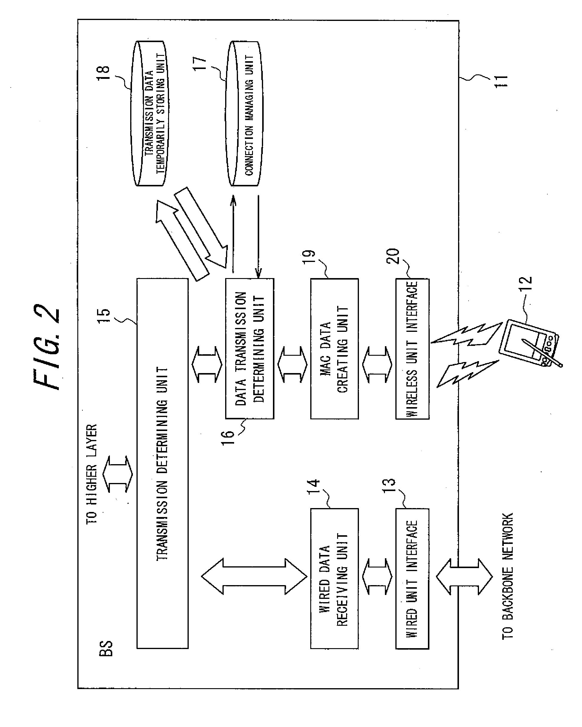
[0065]Shown in FIG. 2 is a block diagram illustrating a configuration of the base station apparatus used for the communication system in accordance with the present invention. As shown in FIG. 2, the BS 11 is provided with a wired unit interface 13, a wired data receiving unit 14, a transmission determining unit 15, a data transmission determining unit 16, a connection managing unit 17, a transmission data temporarily storing unit 18, a MAC (Media Access Code) data creating unit (data transmitting unit) 19, and a wireless unit interface 20.

[0066]The wired unit interface 13 serves as a physical interface with a wired network (such as Ethernet (TM), for example) and is connected to a backbone network. The wired data receiving unit 14 transmits and receives packets with the wired unit interface 13. The wired unit interface 13 and the wired data receiving unit 14 serve as a data obtaining unit for obtaining data for the first session from the network.

[0067]The transmission determining u...

second embodiment

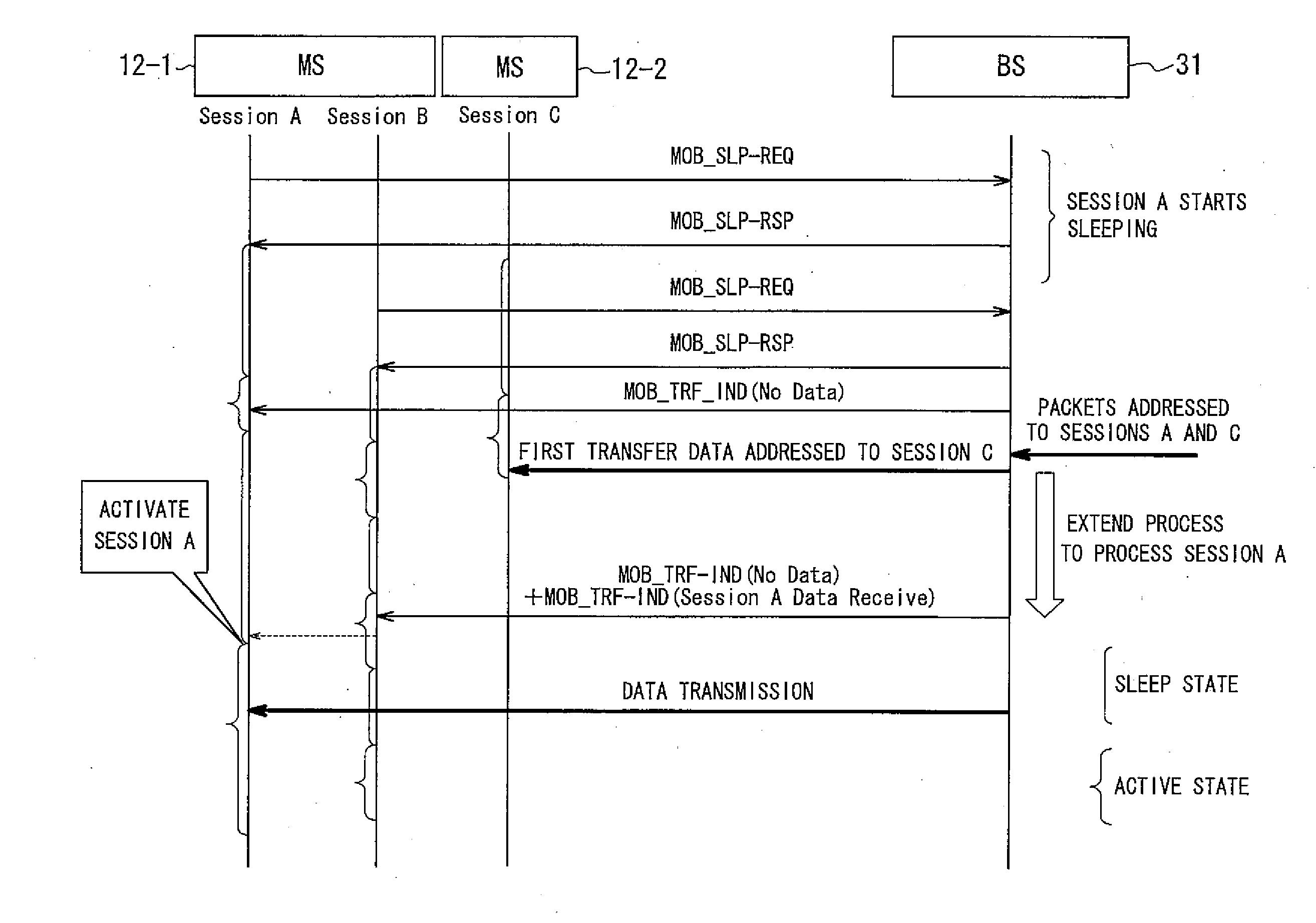
[0113]Next explanations of a communication method of the communication system in accordance with the second embodiment are given.

[0114]First, when the BS 31 receives a communication start request from the MS 12, the data transmission determining unit 16 transmits a packet notifying a MAC address, for instance, which uniquely distinguishes the MS 12 to the mobile terminal managing server 35 in order to obtain the information on the service type of the MS 12. The mobile terminal managing server 35 sends back the service type of the MS 12 from the information notified. The data transmission determining unit 16 stores the information on the service type in the mobile terminal service managing unit 32.

[0115]The process until the data transmission determining unit 16 obtains data arrived at the wired unit interface 13 is the same as that of the first embodiment.

[0116]Here is a case in which data for the first mobile terminal apparatus (MS) 12-1 and data for the second mobile terminal appa...


PUM


Abstract

A BS 11 recognizes states of a first session and a second session and instructs an MS 12 to change a state of the first session via the second session when the BS 11 receives data for the first session from a network while the first session is in the sleep state and the second session is in the active state. When the MS 12 changes the first session to be in the active state before a lapse of predetermined time interval when receiving the instruction from the BS 11, the BS 11 transmits the data for the first session to the MS 12 via the first session changed to be in the active state.

Description

TECHNICAL FIELD[0001]The present invention relates to a communication method and a communication system capable of communicating in a plurality of sessions between a communication terminal apparatus and a base station apparatus, and to the communication terminal apparatus and the base station apparatus used for the communication system.BACKGROUND ART[0002]As a communication system for communication between a communication terminal apparatus and a base station apparatus, disclosed in Patent Document 1 is a communication system to control power supply in a relay apparatus (base station, station) having a plurality of interfaces. In the case of controlling power supply in a relay apparatus having a plurality of interfaces, although a wired interface (IEEE (Institute Electrical and Electronics Engineers) 1394) and a wireless interface of the relay apparatus of the conventional art have a wired standby means and a wireless standby means respectively, there is no comprehensive power contr...

Claims


Application Information

Patent Timeline
Patent Type & Authority Applications(United States)
IPC IPC(8): H04M3/00H04B1/38H04L69/14H04W28/00H04W52/02H04W72/04H04W84/12
CPCH04W52/0216Y02B60/50H04W76/048H04W76/025H04W76/15H04W76/28Y02D30/70
Inventor TACHIKAWA, HITOYA
Owner KYOCERA CORP
Why Eureka
Try Eureka