Method for controlling a hybrid drive

a hybrid drive and drive technology, applied in the direction of engine-driven generator propulsion, mechanical equipment, transportation and packaging, etc., can solve the problem of inability to synchronize during operation, and achieve the effect of broad tolerance range and improved clutching operation

Inactive Publication Date: 2010-03-04
ROBERT BOSCH GMBH
View PDF10 Cites 40 Cited by
  • Summary
  • Abstract
  • Description
  • Claims
  • Application Information

AI Technical Summary

Benefits of technology

[0004]Example embodiments of the present invention make it possible to improve the clutching operation in a vehicle which is equipped with a hybrid drive designed as a parallel hybrid. An additional clutch designed as a proportional clutch is provided here between the internal combustion engine and an electric machine. A configuration of this type allows the vehicle to be driven using the electric machine in the disengaged state of this additional clutch. The problem here is that in the event of increased power requirement or decreasing charge state of the battery, the internal combustion engine must be started without causing interference in the drive train. The start of the internal combustion engine is achieved by engaging this additional clutch. This clutch must, however, be controlled in such a way that, on the one hand, the torque is sufficient to bring the internal combustion engine to a rotational speed required for a successful start. On the other hand, the torque used for accelerating the internal combustion engine must be the lowest possible, since it must be additionally applied by the electric machine and kept in reserve. The present invention makes it possible to optimize this clutching operation, although the said clutch type has a broad tolerance range due to manufacturing tolerances, temperature effects, and aging effects. Furthermore, changes in the torque of the internal combustion engine due to temperature and aging may also be taken into account.

Problems solved by technology

However, since in such devices the electric machine is fixedly connected to the crankshaft of the vehicle, the problem of synchronization during operation does not exist.
The problem here is that in the event of increased power requirement or decreasing charge state of the battery, the internal combustion engine must be started without causing interference in the drive train.

Method used


Image

  • Method for controlling a hybrid drive
  • Method for controlling a hybrid drive
  • Method for controlling a hybrid drive

Examples


Embodiment Construction

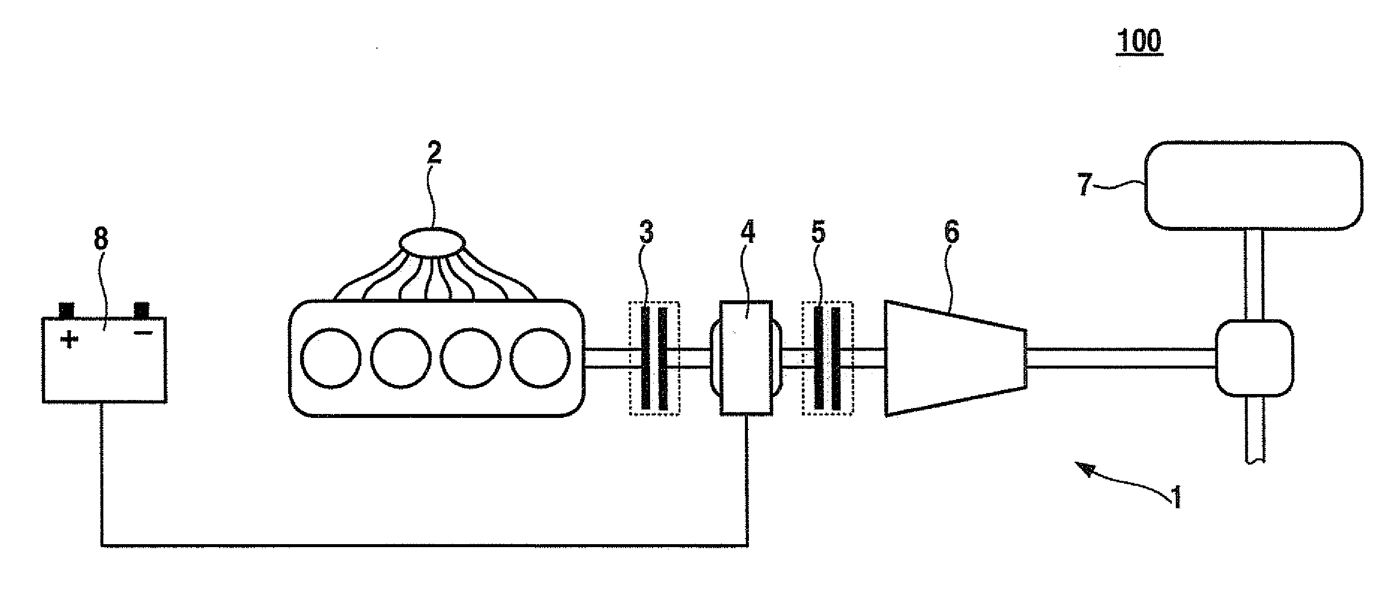
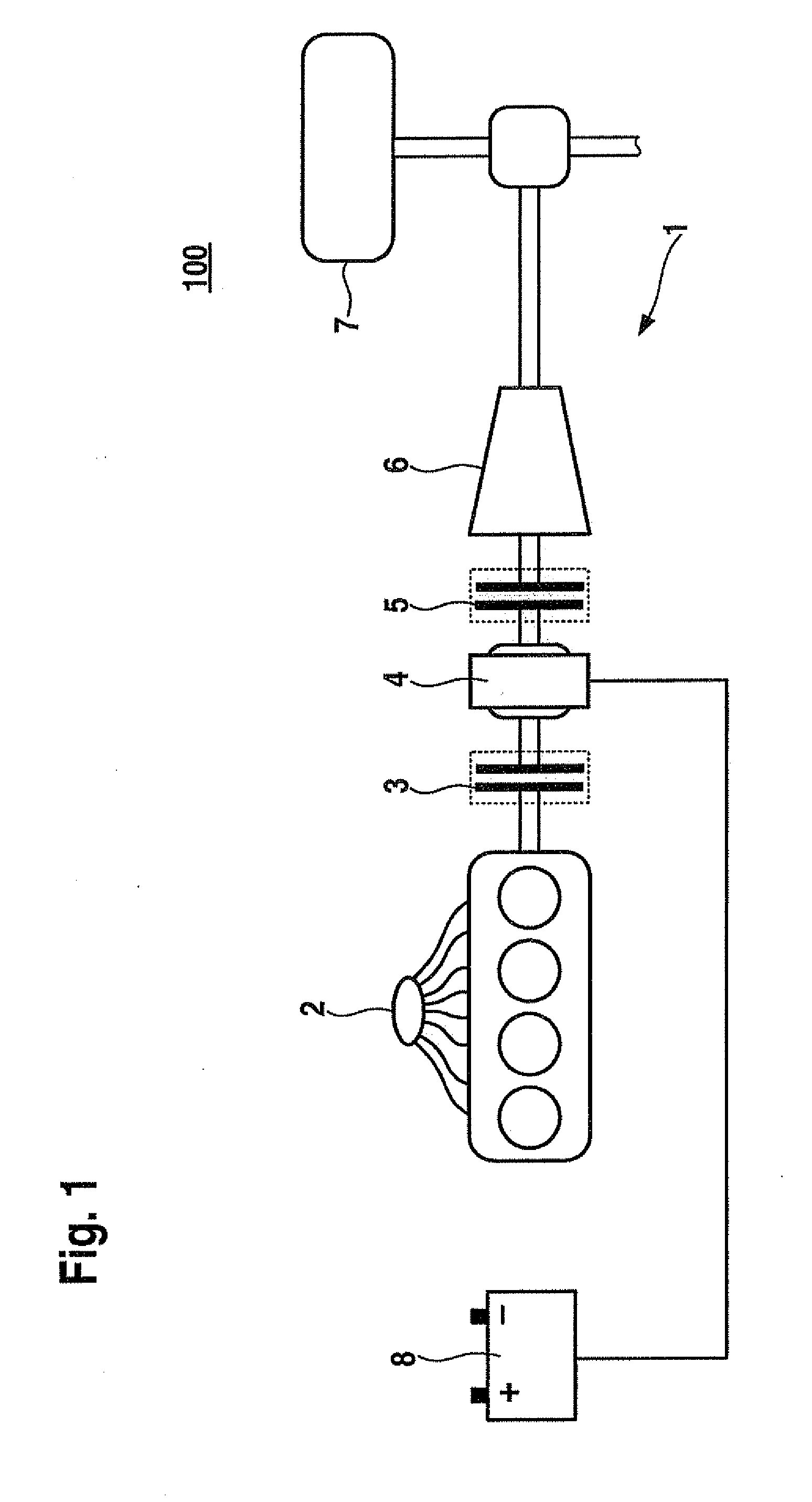
[0014]Example embodiments of the present invention are elucidated in greater detail below with reference to the drawings. FIG. 1 schematically shows a vehicle 100 having a hybrid drive 1. Hybrid drive 1 includes a conventional internal combustion engine 2 and an electric machine 4. A first clutch 5 is situated between electric machine 4 and the schematically represented drive train identified by reference numeral 6. A second clutch 3 is situated between internal combustion engine 2 and electric machine 4. This is preferably a proportional clutch. The chassis of vehicle 100 is indicated by a wheel 7 and a portion of an axle including a differential. A battery supplying electric machine 4 with power is identified by reference numeral 8. Further components of the vehicle electrical system are not illustrated in FIG. 1. Hybrid drive 1 illustrated in FIG. 1 allows vehicle 100 to be driven electrically only by electric machine 4. In this case second clutch 3 situated between internal comb...


PUM


Abstract

A method is for controlling a hybrid drive of a vehicle, which includes at least one internal combustion engine and at least one electric machine, having a first clutch situated between the electric machine and the drive train of the vehicle and a second clutch situated between the electric machine and the internal combustion engine. In the method, a predefinable clutch torque is applied to the second clutch for a start of the internal combustion engine by the operating electric machine, the rotational speed of the internal combustion engine is monitored, and the clutch torque is incremented to a higher value if the rotational speed of the internal combustion engine is less than a predefinable threshold value within a predefinable time interval.

Description

FIELD OF THE INVENTION[0001]The present invention relates to a method for controlling a hybrid drive of a vehicle.BACKGROUND INFORMATION[0002]The generic hybrid drive includes at least one internal combustion engine, at least one electric machine, and at least one clutch between the internal combustion engine and the electric machine, as well as between the electric machine and the downstream drive train of the vehicle. As the existing drive arrangements in the automobile industry regarding consumption optimization, emission reduction, and the improvement of the subjective driving experience are being refined, hybrid drives are becoming more and more important. They have, in addition to the internal combustion engine, at least one additional drive source which is not operated using fossil fuels. Using an appropriate operating strategy, the advantages of the different drive sources may be made optimum use of, while compensating for their disadvantages. The combination of an internal ...

Claims


Application Information

Patent Timeline
Patent Type & Authority Applications(United States)
IPC IPC(8): B60W20/00B60W10/02B60W10/08B60W10/06B60L50/16
CPCB60K6/48B60W10/02B60W10/06B60W10/08B60W20/00B60W2510/0241Y10T477/32Y02T10/6221Y02T10/6286B60L11/12B60L11/14Y10T477/26Y10T477/79B60W2710/025B60L50/16Y02T10/62Y02T10/7072B60K2006/268B60W2050/0052B60W20/40Y02T10/70
Inventor SCHENK, RENEKAEFER, OLIVERJUENEMANN, THORSTEN
Owner ROBERT BOSCH GMBH
Why Eureka
Try Eureka