Drug Heating Cycle Limiter For Injection Device

a technology of heating cycle limiter and injection device, which is applied in the direction of contraceptive devices, liquid handling, instruments, etc., can solve the problems of uncontrollable fluid flow rate, subject to parallax error, and inaccurate volume injection

Inactive Publication Date: 2010-03-04
ALCON RES LTD
View PDF3 Cites 36 Cited by
  • Summary
  • Abstract
  • Description
  • Claims
  • Application Information

AI Technical Summary

Problems solved by technology

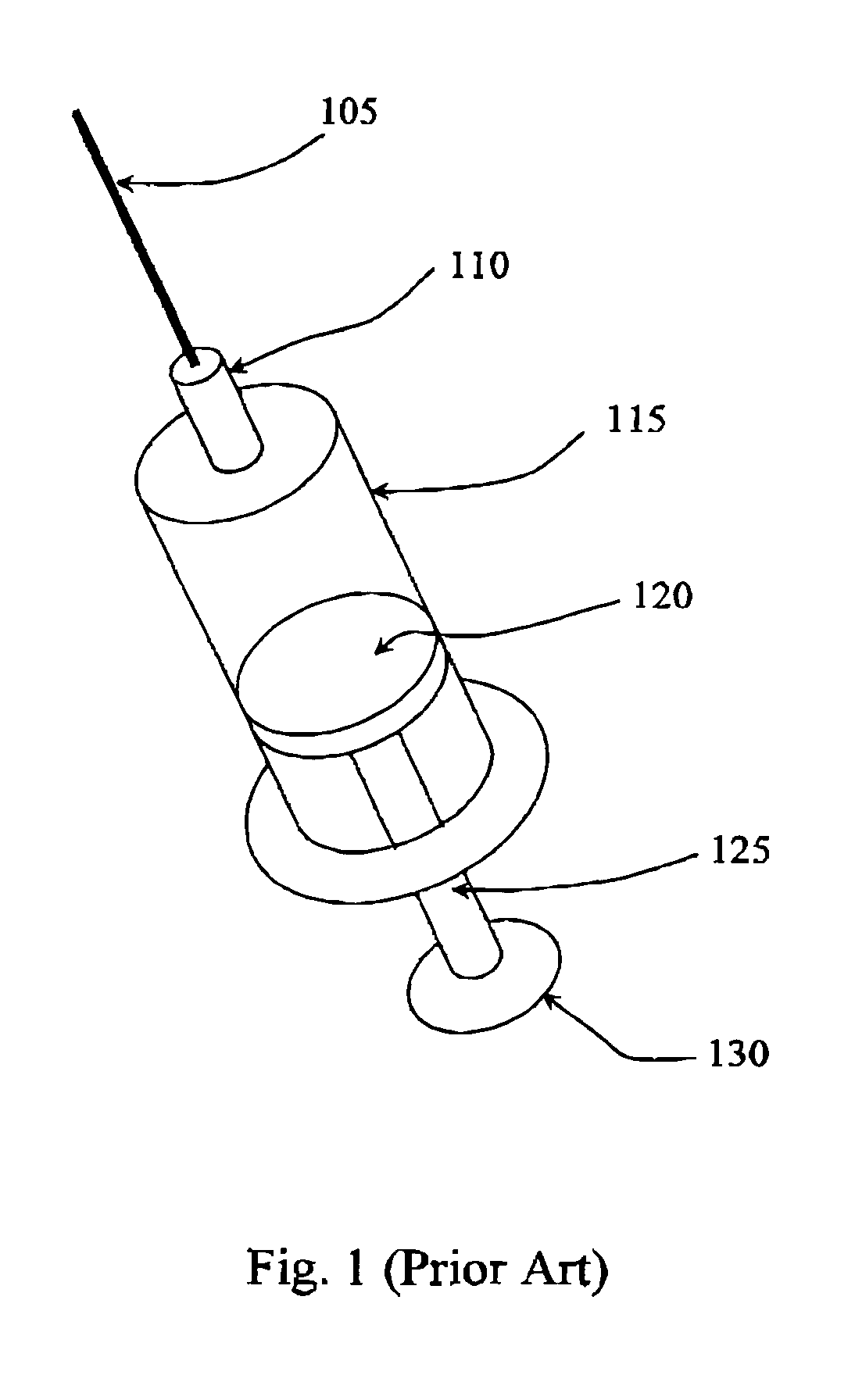
The volume injected is typically not controlled in an accurate manner because reading the vernier is subject to parallax error.
Fluid flow rates are uncontrolled and tissue damage may occur due to an “unsteady” injection.

Method used


Image

  • Drug Heating Cycle Limiter For Injection Device
  • Drug Heating Cycle Limiter For Injection Device
  • Drug Heating Cycle Limiter For Injection Device

Examples


Embodiment Construction

[0023]Reference is now made in detail to the exemplary embodiments of the invention, examples of which are illustrated in the accompanying figures. Wherever possible, the same reference numbers are used throughout the figures to refer to the same or like parts.

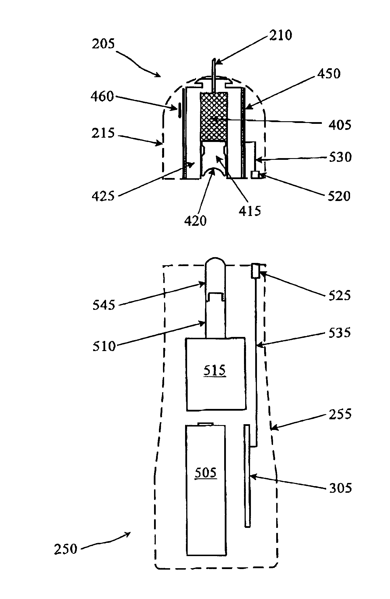
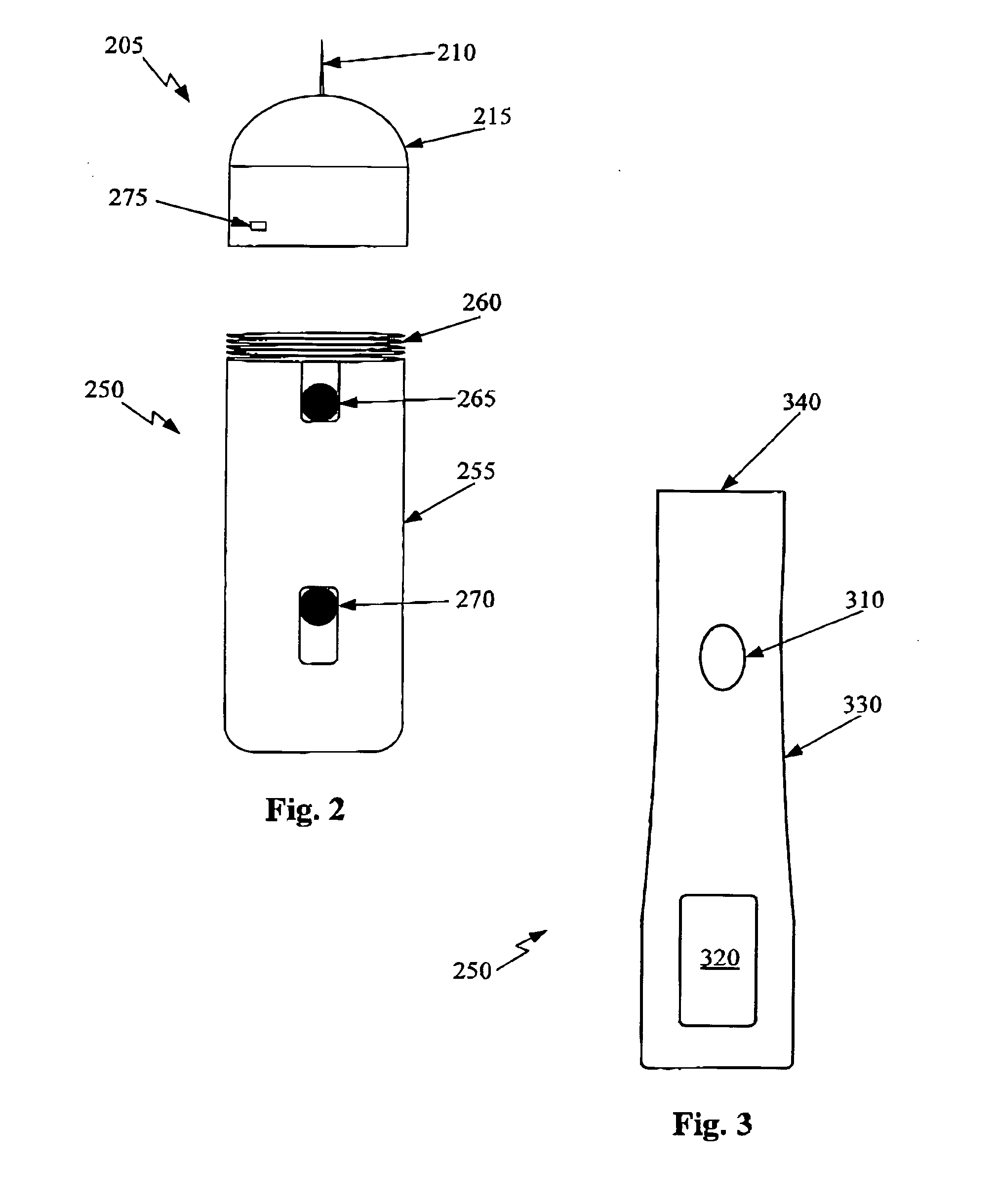
[0024]FIG. 2 depicts one view of an ophthalmic medical device including a disposable tip segment and a limited reuse assembly according to an embodiment of the present invention. In FIG. 2, the medical device includes a tip segment 205 and a limited reuse assembly 250. The tip segment 205 includes a needle 210, a housing 215, and an optional light 275. The limited reuse assembly 250 includes a housing 255, a switch 270, a lock mechanism 265, and a threaded portion 260.

[0025]Tip segment 205 is capable of being connected to and removed from limited reuse assembly 250. In this embodiment, tip segment 205 has a threaded portion on an interior surface of housing 215 that screws onto the threaded portion 260 of limited reuse assembl...


PUM


Abstract

An injection assembly includes a dispensing chamber housing, a temperature control device, a thermal sensor, a switch, and a controller. The dispensing chamber housing has an inner surface and an outer surface. The inner surface partially defines a dispensing chamber for receiving a quantity of a substance. The temperature control device at least partially surrounds the dispensing chamber housing and alters a temperature of a substance in the dispensing chamber. The thermal sensor is located near the temperature control device and reads a temperature near the temperature control device. The switch is coupled to the temperature control device. The controller controls the temperature control device and the switch such that a first voltage is applied to the temperature control device until the temperature control device reaches a desired temperature, and a second voltage is applied to the temperature control device thereafter to maintain the temperature control device at the desired temperature.

Description

RELATED APPLICATIONS[0001]This application is a continuation-in-part of U.S. patent application Ser. No. 11 / 581,629 filed Oct. 16, 2006, U.S. patent application Ser. No. 11 / 581,630 filed Oct. 16, 2006, U.S. patent application Ser. No. 11 / 581,591 filed Oct. 16, 2006, and is related to U.S. patent application Ser. No. 11 / 435,906 filed May 17, 2006.BACKGROUND OF THE INVENTION[0002]The present invention relates to a single-use medical device and more particularly to a two-piece ophthalmic injection device with a disposable tip end containing a temperature control device and temperature sensor assembly.[0003]Several diseases and conditions of the posterior segment of the eye threaten vision. Age related macular degeneration (ARMD), choroidal neovascularization (CNV), retinopathies (e.g., diabetic retinopathy, vitreoretinopathy), retinitis (e.g., cytomegalovirus (CMV) retinitis), uveitis, macular edema, glaucoma, and neuropathies are several examples.[0004]These, and other diseases, can b...

Claims


Application Information

Patent Timeline
Patent Type & Authority Applications(United States)
IPC IPC(8): A61M5/44B67D7/82A61F7/12
CPCA61F9/0017A61M2005/14268A61M5/20A61M5/3129A61M5/31511A61M5/445A61M2205/3368A61M2205/3653A61M2205/50A61M2205/6027A61M2205/8206A61M2210/0612A61M5/1413A61M5/14546A61M5/14566A61M5/14244A61M5/14526A61F9/0008A61M5/178A61M31/00A61M35/003A61M2005/14284A61M2205/52
Inventor DOS SANTOS, CESARIO
Owner ALCON RES LTD
Why Eureka
Try Eureka