Flexible heart valve and associated connecting band

a heart valve, flexible technology, applied in the field of prosthetic heart valves, can solve the problems of increasing the pressure drop therethrough, and achieve the effect of reducing the pressure loss

Inactive Publication Date: 2010-03-04
EDWARDS LIFESCIENCES CORP
View PDF12 Cites 4 Cited by
  • Summary
  • Abstract
  • Description
  • Claims
  • Application Information

AI Technical Summary

Benefits of technology

[0008]The present invention allows the prosthesis to follow the aortic wall motion as well as that of the annulus during systole and diastole phases, thus reducing the loss in pressure caused by restriction of such motions. The solution is a heart valve having a plurality of leaflets, preferably three, directly sutured to the aortic wall, replacing the native valve.
[0009]The present invention provides a heart valve including a flexible wireform or stent that allows relative cusp movement or pivoting. The continuous maintenance of leaflet orientation at the commissures provides durability and predictability. Though the leaflets are not wholly independent, they are allowed to move in regions of greatest anatomical motion.
[0016]In another aspect of the present invention, a holder is provided for mounting the flexible heart valve. The holder includes a central hub with a plurality of radially outward upper legs, and a plurality of lower legs angled downward and outward. The upper and lower legs are adapted to connect to the alternating cusps and commissures of a flexible valve so as to maintain the position of the valve during implantation.
[0020]The present invention provides a holder for a heart valve including a flexible stent that allows relative cusp movement or pivoting. The continuous maintenance of leaflet orientation at the commissures provides durability and predictability. Though the leaflets are not wholly independent, they are allowed to move in regions of greatest anatomical motion. The heart valve may be highly flexible and include a stent / leaflet subassembly having a peripheral stent and a plurality of leaflets disposed therewithin. The stent / leaflet subassembly defines alternating cusps and the commissures. A connecting band may be attached to the stent / leaflet subassembly and follows the alternating cusps and commissures. The band may include a free edge extending from the stent for connecting the heart valve to an anatomical orifice.
[0026]The holder preferably includes structure for substantially preventing torsional deformation of the flexible heart valve during implantation. The holder further may include a valve contacting portion having a generally continuous curvilinear structure conforming to the periphery of the valve and defining the alternating cusp and commissure supports. A central hub with a plurality of legs angled downward and outward may be connected to the cusp supports. In one version, the valve contacting portion is integrally formed separate from the legs, while in another the valve contacting portion is formed of a plurality of separate pieces, each piece defining at least a part of one of the legs. Each separate piece may define a half of two adjacent cusp supports, and may be formed of a wire.
[0030]In another aspect of the present invention, a holder is provided for mounting the flexible heart valve. The holder includes a central hub with a plurality of radially outward upper legs, and a plurality of lower legs angled downward and outward. The upper and lower legs are adapted to connect to the alternating cusps and commissures of a flexible valve so as to maintain the position of the valve during implantation.

Problems solved by technology

Because of the inherent rigidity in conventional heart valves, the natural dilatation of the annulus is restricted, imposing an artificial narrowing of the orifice, and increasing the pressure drop therethrough.

Method used


Image

  • Flexible heart valve and associated connecting band
  • Flexible heart valve and associated connecting band
  • Flexible heart valve and associated connecting band

Examples


Embodiment Construction

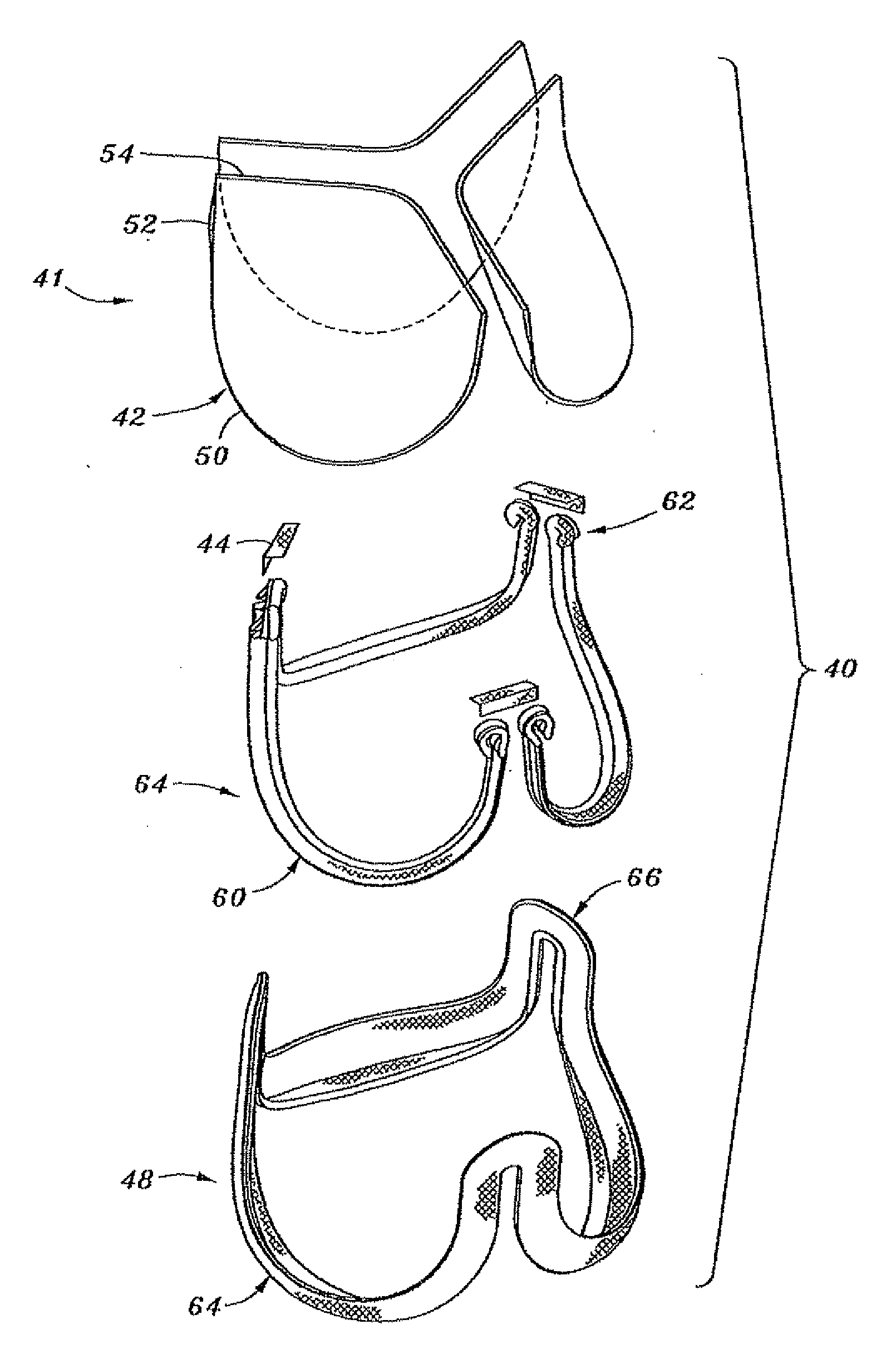
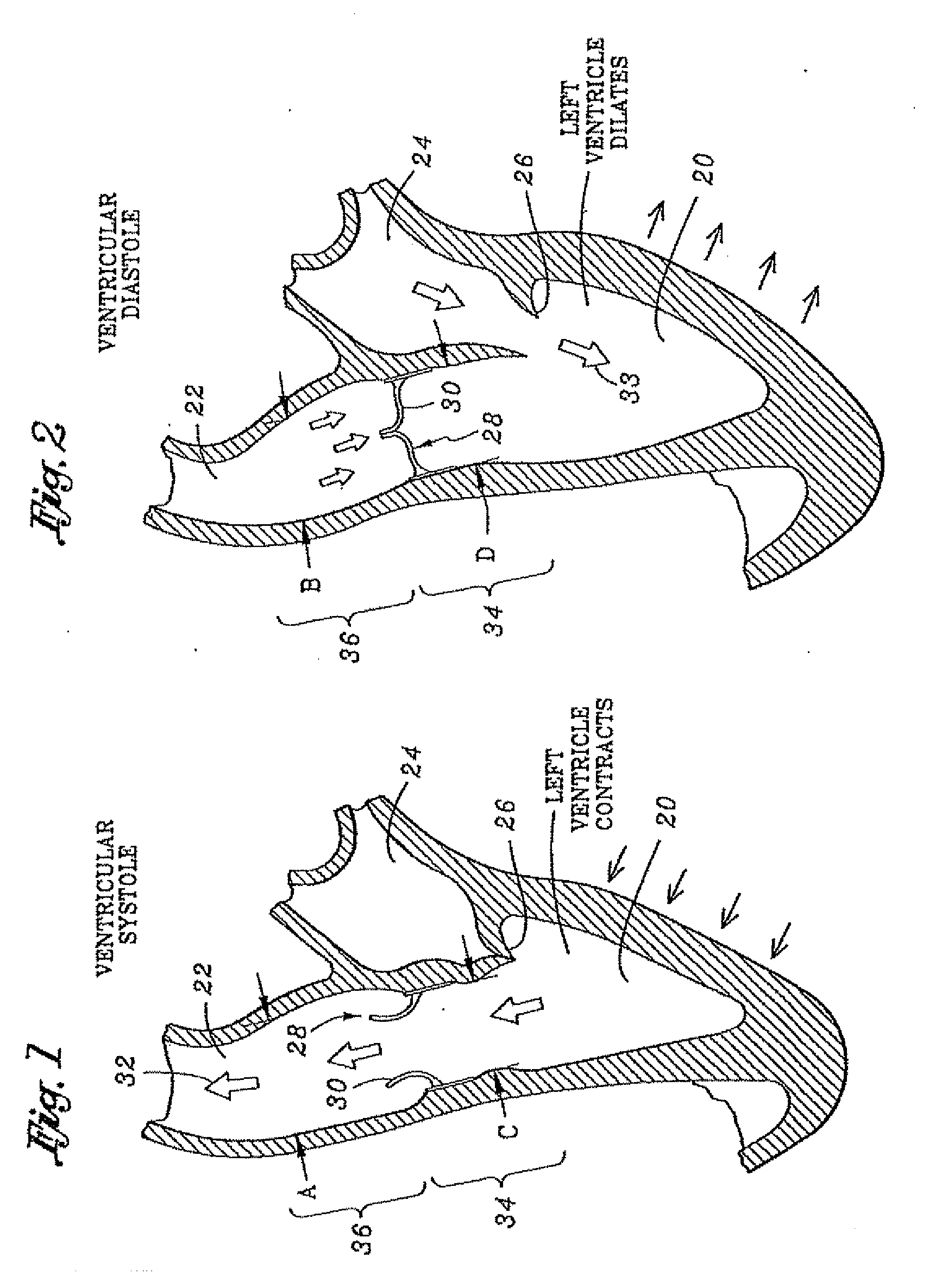
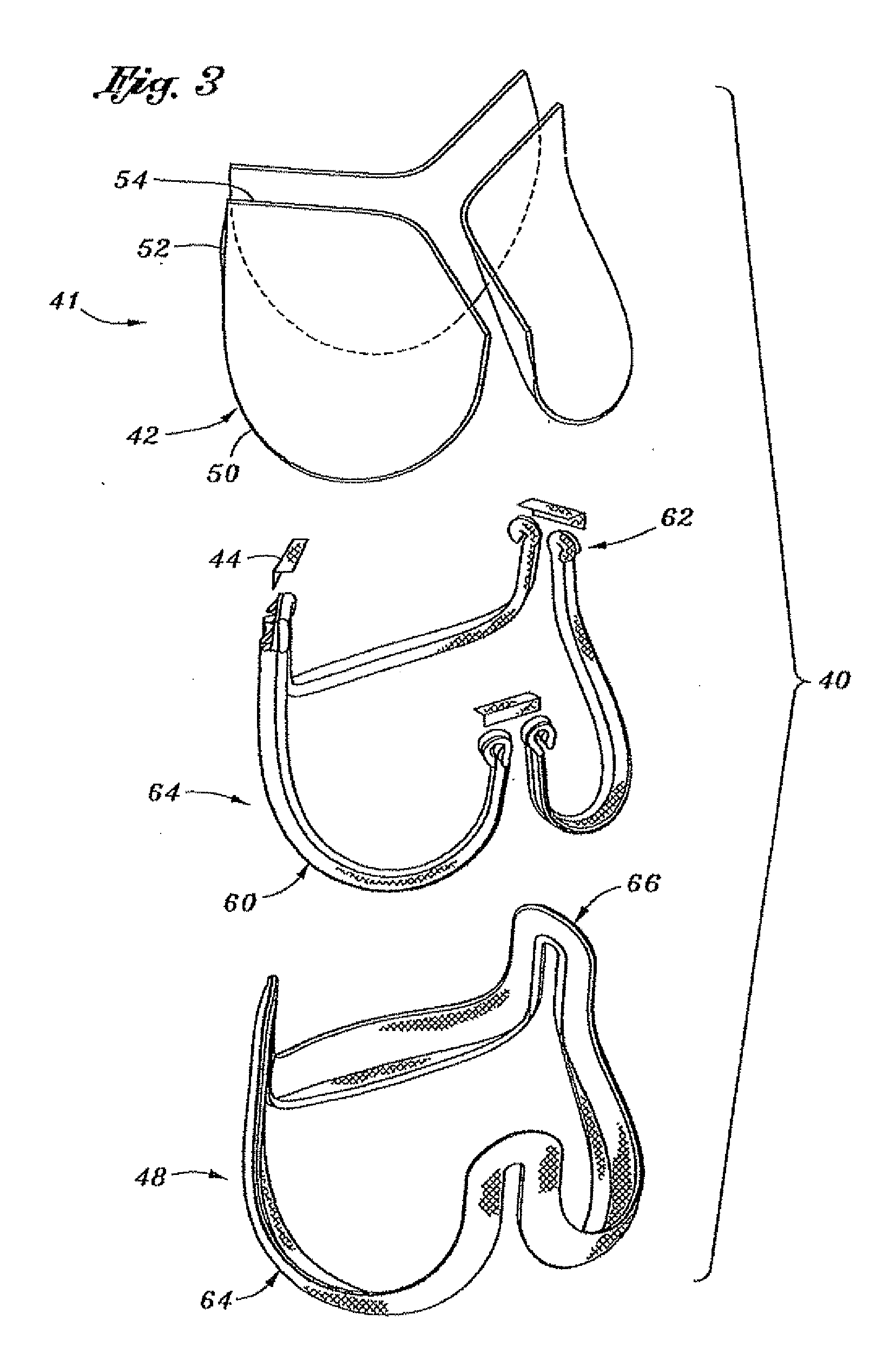
[0081]The present invention provides a highly flexible aortic heart valve that is attached generally along a scalloped or undulating perimeter downstream from where the natural leaflets were originally attached. The natural leaflets include arcuate cusp portions separated by common commissure portions. If the natural valve has three leaflets, and has a vertically oriented flow axis, the leaflets are evenly distributed circumferentially 120° apart with lower cusp portions and upstanding commissure portions. The commissure portions are connected between the cusp portions and are generally axially aligned along the aortic wall. The annular root of an aortic valve is composed of fibrous tissue and generally conforms to the undulating perimeter of the valve to support the leaflets. In this respect, implanting the aortic heart valve of the present invention involves excising the natural leaflets and attaching the prosthetic heart valve proximate the fibrous annulus, but also in part up th...


PUM


Abstract

A highly flexible tissue-type heart valve is disclosed having a structural stent in a generally cylindrical configuration with cusps and commissures that are permitted to move radially. The stent commissures are constructed so that the cusps are pivotably or flexibly coupled together at the commissures to permit relative movement therebetween. The stent may be cloth-covered and may be a single element or may be made in three separate elements for a three cusp valve, each element having a cusp portion and two commissure portions; adjacent commissure portions for each pair of adjacent stent element combining to form the stent commissures. If the stent has separate elements their commissure portions may be pivotably or flexible coupled, or may be designed to completely separate into independent leaflets at bioresorbable couples. The cloth covering may have an outwardly projecting flap that mates with valve leaflets (e.g., pericardial leaflets) along the cusps and commissures. A connecting band may be provided that follows the cusps and commissures and extends outwardly. The valve is connected to the natural tissue along the undulating connecting band using conventional techniques, such as sutures. The connecting band may be a cloth-covered silicon member and attaches to the underside of the valve at the cusps to provide support to the stent and to the outer side of the valve at the commissures. The connecting band includes commissure portions defining generally axial gaps that help permit flexing of the valve.

Description

RELATED APPLICATIONS[0001]The present application is a continuation of U.S. application Ser. No. 12 / 391,212 filed Feb. 23, 2009, entitled “FLEXIBLE HEART VALVE AND ASSOCIATED CONNECTING BAND”; U.S. application Ser. No. 12 / 188,826 filed Aug. 8, 2008, entitled “FLEXIBLE HEART VALVE AND ASSOCIATED CONNECTING BAND”; which is a continuation of U.S. application Ser. No. 10 / 729,035, filed Dec. 5, 2003, entitled FLEXIBLE HEART VALVE AND ASSOCIATED CONNECTING BAND, which is a continuation of U.S. application Ser. No. 09 / 847,930, filed May 3, 2001, entitled HOLDER FOR FLEXIBLE HEART VALVE, which is a continuation-in-part of U.S. application Ser. No. 09 / 332,759, filed Jun. 14, 1999, entitled FLEXIBLE HEART VALVE, now U.S. Pat. No. 6,558,418, which claims priority under 35 U.S.C §119(e) to provisional application No. 60 / 117,445, filed on Jan. 26, 1999, the disclosures of which are expressly incorporated herein by reference.FIELD OF THE INVENTION[0002]The present invention relates to prosthetic ...

Claims


Application Information

Patent Timeline
Patent Type & Authority Applications(United States)
IPC IPC(8): A61F2/06A61F2/24
CPCA61F2/2412A61F2/2418A61F2220/0075A61F2220/005A61F2220/0066A61F2/2427
Inventor CARPENTIER, ALAIN F.SCHRECK, STEFAN G.RHEE, RICHARD S.NGUYEN-THIEN-NHON, DIANALAM, HUNG LYRECKTENWALD, WILLIAM J.FRATER, ROBERT
Owner EDWARDS LIFESCIENCES CORP
Why Eureka
Try Eureka