Automatic finishing machine and control method thereof

Active Publication Date: 2010-03-04
KAWASAKI HEAVY IND LTD
View PDF11 Cites 22 Cited by
  • Summary
  • Abstract
  • Description
  • Claims
  • Application Information

AI Technical Summary

Benefits of technology

[0030]Similar to the above control method of this invention, this automatic finishing machine can significantly reduce the time required for teaching the robot on the production site, as well as can substantially eliminate the need for special skill or technique for the teaching operation. Additionally, this machine can perform the highly accurate and stable automatic finishing process.
[0031]Thus, according to the automatic finishing machine and method of controlling this machine, the shape data or teaching data, on the three-dimensional model of the unfinished work under the ideal environment, can be stored, in advanc

Problems solved by technology

In addition, in the case of such a manual-based method, the operator should teach the robot while repeating try and error, thus requiring unduly much time.
Therefore, the production line should be stopped for a long period of time, leading to substantial d

Method used


Image

  • Automatic finishing machine and control method thereof
  • Automatic finishing machine and control method thereof
  • Automatic finishing machine and control method thereof

Examples


Example

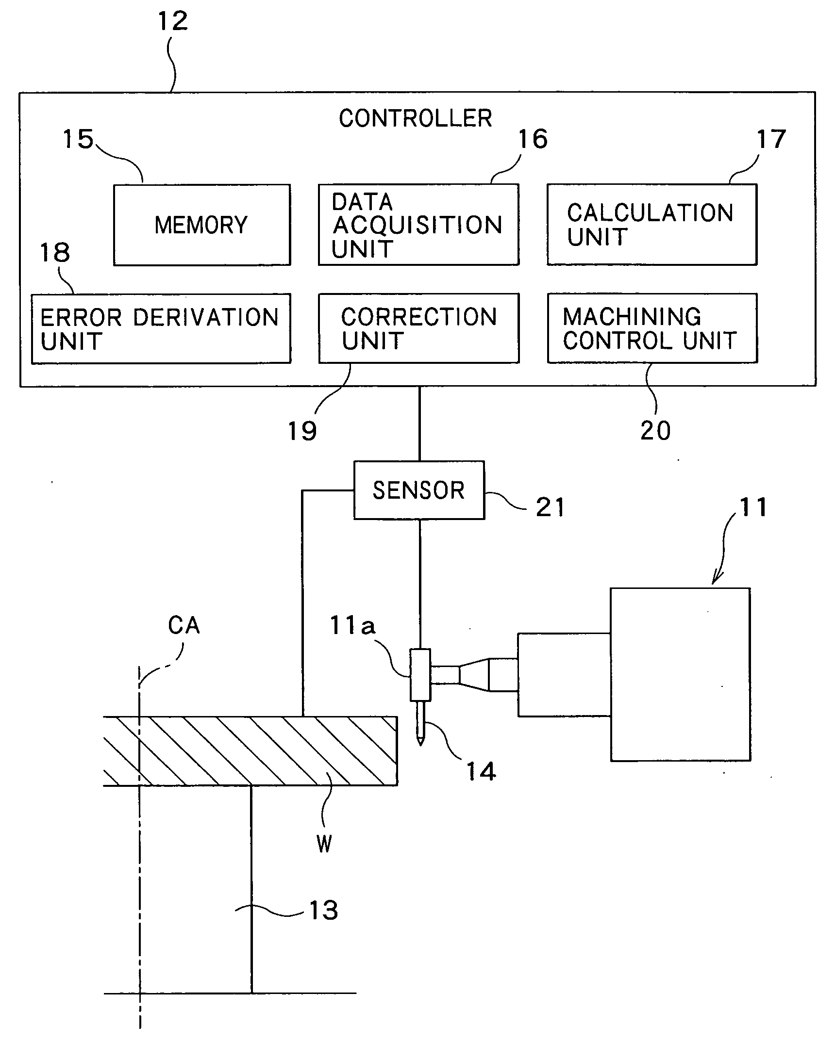
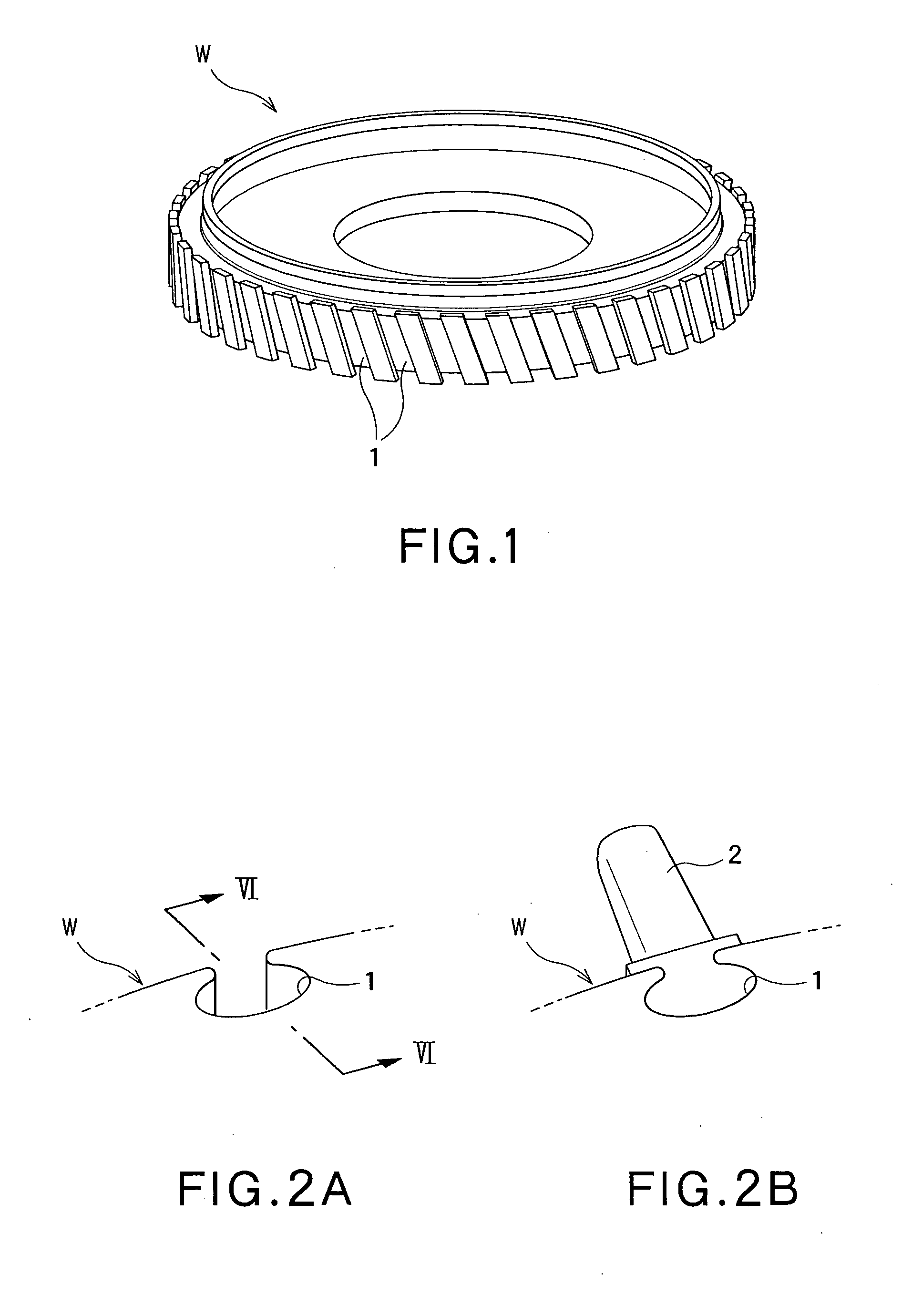
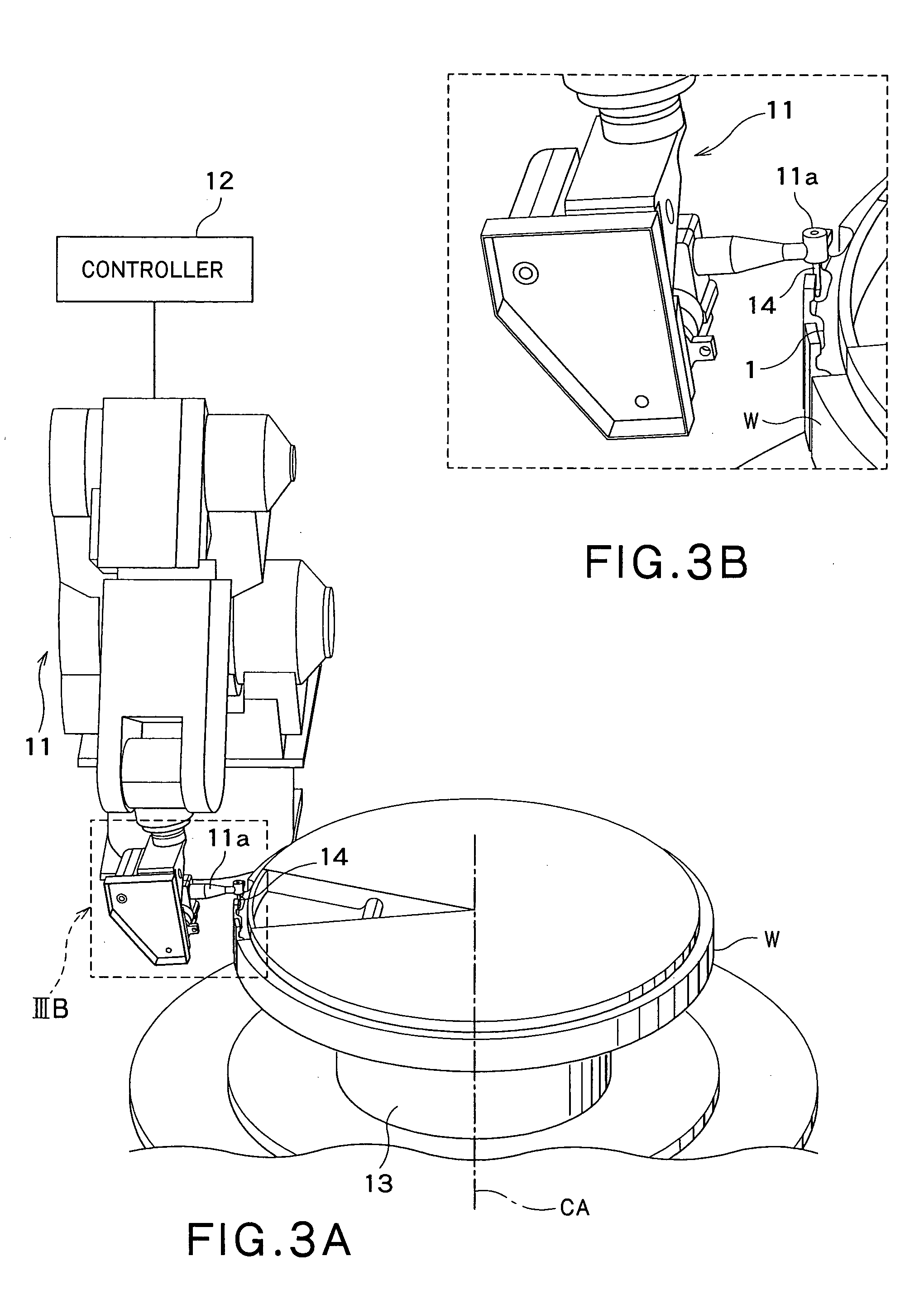
[0042]Hereinafter, one preferred embodiment of the present invention will be described with reference to the drawings. As shown in FIG. 1, the work W, to which the finishing process is provided, is a disk-like part constituting a compressor of a jet engine. This work W has a plurality of attachment grooves 1 formed in an outer circumference thereof. Each of the grooves 1 is configured to be engaged with a blade 2 (see FIG. 2), and is provided to the work W in an outer-circumferential direction at an equal interval. In this embodiment, the finishing process using the automatic finishing machine is performed to chamfer each attachment groove 1 or the like after the disk-like work W is machined. FIG. 2A is an enlarged schematic and perspective view of one of the grooves 1 formed in the work W shown in FIG. 1, and FIG. 2B is a perspective view showing a state, in which the blade is fitted in the groove 1 of the work W after the work W is machined.

[0043]Referring to FIGS. 3A and 3B, the ...


PUM


Abstract

This method controls an automatic finishing machine using a robot with a tool through a model storage step, a data acquisition step, a calculation step, an error derivation step, a correction step and a machining step. In the model storage step, shape data of an unfinished work or data of a three-dimensional model is stored in a memory. In the data acquisition step, the tool is brought into contact with the unfinished work W, thereby obtaining measurement data. Then, in the calculation step, actual-position data on a comparative object point is calculated based on the measurement data. Subsequently, in the error derivation step, a data difference between the calculated actual-position data and position data on the comparative object point in the three-dimensional model is obtained. Thereafter, in the correction step, teaching data indicative of the position of the tool corresponding to the shape data of the three-dimensional model is corrected, based on the data difference. Finally, in the machining step, the finishing process is performed, while the robot (11) is controlled, based on the corrected teaching data.

Description

CROSS REFERENCE TO RELATED APPLICATIONS[0001]This application is based upon the prior Japanese Patent Application No. 2008-217590 filed on Aug. 27, 2008, the entire contents of which are incorporated herein by reference.TECHNICAL FIELD[0002]The present invention relates to an automatic finishing machine adapted for providing a finishing process to a work by using a robot having a tool, and also relates to a method for controlling this machine.BACKGROUND ART[0003]In a procedure for manufacturing a product, a speed of a machining process, such as turning or lathe turning, has been markedly increased, with recent development of machines used for the process. As compared with the development of the machines related to such process, a finishing process has not been so mechanized, and is still mostly depending on manual labor. As an example of automation currently implemented for such a finishing process, it is known that the automatic finishing machine employing an industrial robot is us...

Claims


Application Information

Patent Timeline
IPC IPC(8): G05B15/00
CPCG05B2219/36504G05B19/4083
Inventor ICHIKAWA, YOSHIHIRO
Owner KAWASAKI HEAVY IND LTD
Why Eureka
Try Eureka