Piezoelectric Transducers and Inertial Sensors using Piezoelectric Transducers

a piezoelectric transducer and inertial sensor technology, applied in the field of microelectromechanical inertial sensor, can solve the problems of increasing the cost of the resulting mems-based device, reducing the accuracy of the piezoelectric transducer, and not being particularly compatible with the widely used standard cmos process

Inactive Publication Date: 2010-03-11
ANALOG DEVICES INC
View PDF3 Cites 51 Cited by
  • Summary
  • Abstract
  • Description
  • Claims
  • Application Information

AI Technical Summary

Benefits of technology

[0010]Embodiments of a piezoelectric transducer of this invention permit transferring energy, through piezoelectric effect, between electrostatic energy associated with voltage differential between the top and bottom electrodes of the transducer and mechanical energy associated with deformation of frames of the transducer. In one embodiment, the transducer of the invention comprises a structure made of piezoelectric material that includes a set of substantially flat elongated concentric frames connected by bridges disposed symmetrically about a plane of symmetry of the structure. Such bridges allow the frames to deform in a reference plane which is substantially parallel to top and bottom surfaces of the frames. A set of at least two top electrodes is disposed on the top surfaces of the frames. A set of at least two corresponding bottom electrodes is disposed on the bottom surface of the frames opposite to the first set. Both the top and the bottom set of electrodes are disposed on at least two frames along a path that is symmetric about the plane of symmetry of the structure and crosses some of the bridges. Some of these electrodes may be used to apply a voltage differential between the top and bottom surfaces of the piezoelectric transducer, while some of the electrodes may be configured to sense the changes in motion of the frames of the transducer based on a voltage differential associated with such changes. In some embodiments, the deformation of the frames may be reciprocating, and may be characterized by amplitude that is higher in central portions of the frames than in peripheral portions of the frames.

Problems solved by technology

As would be appreciated by one skilled in the art, currently employed micromachining processes are not particularly compatible with widely used standard CMOS processes such as reactive-ion etch (RIE) or electron-beam milling.
Such incompatibility lengthens and complicates fabrication cycles and increases the cost of the resulting MEMS-based devices.
The air-gaps of MEMS structures are clearly susceptible to contamination with microparticles (during both the manufacturing process and operation) that may permanently incapacitate inertial sensors devices.
Moreover, an electrostatically driven mass or ring in such devices is susceptible to anomalies in charge distribution across a set of driving and sensing electrodes.
In vibrating gyroscopes, the non-uniform charge distribution can contribute to an offset drift and reduce the accuracy and precision of these devices or even nullify their performance.

Method used


Image

  • Piezoelectric Transducers and Inertial Sensors using Piezoelectric Transducers
  • Piezoelectric Transducers and Inertial Sensors using Piezoelectric Transducers
  • Piezoelectric Transducers and Inertial Sensors using Piezoelectric Transducers

Examples


embodiment 60

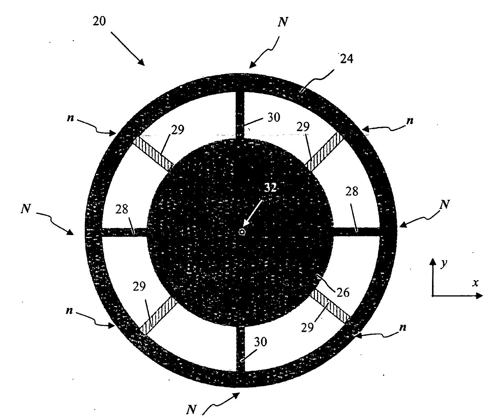
[0042]Configuration of transducers is further discussed with reference to FIGS. 9 and 10, illustrating some exemplary embodiments, with continuing reference to FIG. 8. Although the transducer operation is described below with reference to the driving transducers 50 of FIG. 8, the same description is equally applicable to the sensing transducers 58. FIG. 9A shows, in top view, a piezoelectric frame structure 60 of a transducer 50. As shown, the piezoelectric frame structure is elongated along x-axis, i.e. laterally with respect to a spoke 42 that connects the ring 24 of the gyroscope 40 to the hub 26. FIG. 9B offers a corresponding side view. The structure 60 is characterized by a substantially constant thickness t defined by the top and bottom substantially flat surfaces 46 and 62 that are parallel to a reference plane (the xy-plane in FIG. 9). Although the frame structure 60 is shown to possess two-fold symmetry (about the yz- and xz-planes, each of which is a plane of symmetry of ...

embodiment 80

[0044]It should be appreciated that a transducer of the invention can operate as part of either a driving element, generating an in-plane mode of oscillation of the ring of the inertial sensor as discussed above in reference to FIG. 7, or as part of a sensing element. The operation of a driving transducer of the invention is further discussed in reference to FIGS. 11 and 12, with continuing reference to FIG. 10. FIGS. 11A and 11B schematically illustrate, in side views, a cross-section of a portion of the frame of the embodiment 80 of FIG. 10 with a an electric potential of cyclically alternating polarity applied between the top electrode and the corresponding bottom electrode (in this example, the electrodes 82 and 82′) that sandwich the frame comprised of the piezoelectric material. The instantaneous electrostatic field, associated with the potential difference applied between the electrodes, is denoted as E. It should be appreciated that, to enhance the driving operation of the t...

embodiment 110

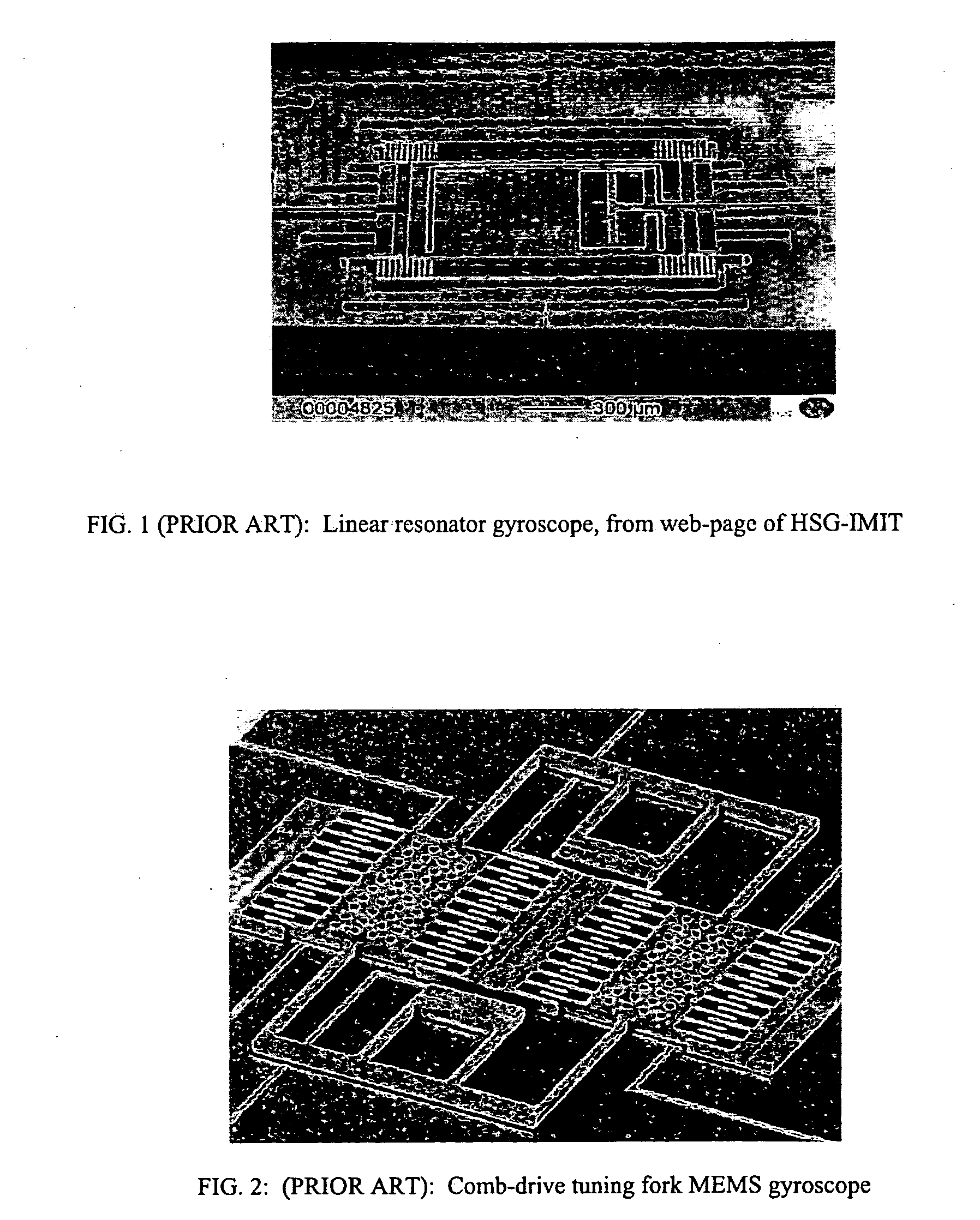
[0051]The embodiments of the invention described above are intended to be merely exemplary; numerous variations and modifications will be apparent to those skilled in the art based on the teachings of this disclosure. Piezoelectric drivers and / or sensors of the type described above (e.g., with reference to FIGS. 6,8-10,13) can be used in other types of inertial sensors and are not limited to ring gyroscopes. For example, piezoelectric transducers of the invention may be used in linearly resonating MEMS-based structures such as linear resonator gyroscopes. Although the operation of the inertial sensor of the invention was described in reference to an embodiment of FIG. 8 containing four driving elements 52 and four sensing elements 54, it should be understood that there is no theoretical limitation on the number of driving and sensing elements or a particular fashion in which the driving elements operate. For example, in reference to FIG. 8, the ring 24 of the inertial sensor may be ...


PUM

PropertyMeasurementUnit
elongationaaaaaaaaaa
symmetryaaaaaaaaaa
electrostatic energyaaaaaaaaaa

Abstract

Transducers comprising a frame structure made of piezoelectric material convert energy, through piezoelectric effect, between electrostatic energy associated with voltage differential between the electrodes sandwiching the frame structure and mechanical energy associated with deformation of the frame structure. Inertial sensors such as gyroscopes and accelerators, including inertial sensors comprising ring resonators, utilize said transducers both to generate oscillations of their resonators and to sense the changes in such oscillations produced, in the sensors' frame of reference, by Coriolis forces appearing due to the movement of the sensors.

Description

TECHNICAL FIELD[0001]The present invention relates generally to inertial sensors, and more particularly to microelectromechanical inertial sensors for measuring a rotational motion, such as ring gyroscopes.BACKGROUND ART[0002]It is known in the prior art to use inertial motion sensors to track the position, orientation, and velocity (linear or angular) of objects in the inertial reference frame, without the need for external references. Inertial motion sensors generally include gyroscopes, accelerators, and other motion-sensing devices. Gyroscopes are well-known and used for measuring or maintaining orientation based on the principles of conservation of angular momentum. Vibrating structure gyroscopes, due to their simplicity and low cost, gained popularity since 1980s over conventional, rotating gyroscopes. The physical principle of a vibrating structure gyroscope is very intelligible: a vibrating object tends to keep vibrating in the same plane as its support is rotated. In engine...

Claims


Application Information

Patent Timeline
Patent Type & Authority Applications(United States)
IPC IPC(8): G01C19/56G01P15/09
CPCG01C19/5677Y10T29/42G01P15/09G01C19/56
Inventor KUANG, JINBOCLARK, WILLIAM ALBERTGEEN, JOHN ALBERT
Owner ANALOG DEVICES INC
Why Eureka
Try Eureka