Piezoelectric pump and fluid transferring system

a fluid transfer system and piezoelectric pump technology, applied in water installations, thin material processing, construction, etc., can solve the problems of difficult to accurately manufacture a piezoelectric pump capable of stable fluid transfer, difficult to integrate high density, and difficult to combine the use of piezoelectric pump and component, so as to achieve stable fluid transfer, maintain uniform stress in the motion part, and achieve the effect of piezoelectric pump

Inactive Publication Date: 2010-03-11
TDK CORPARATION
View PDF0 Cites 12 Cited by
  • Summary
  • Abstract
  • Description
  • Claims
  • Application Information

AI Technical Summary

Benefits of technology

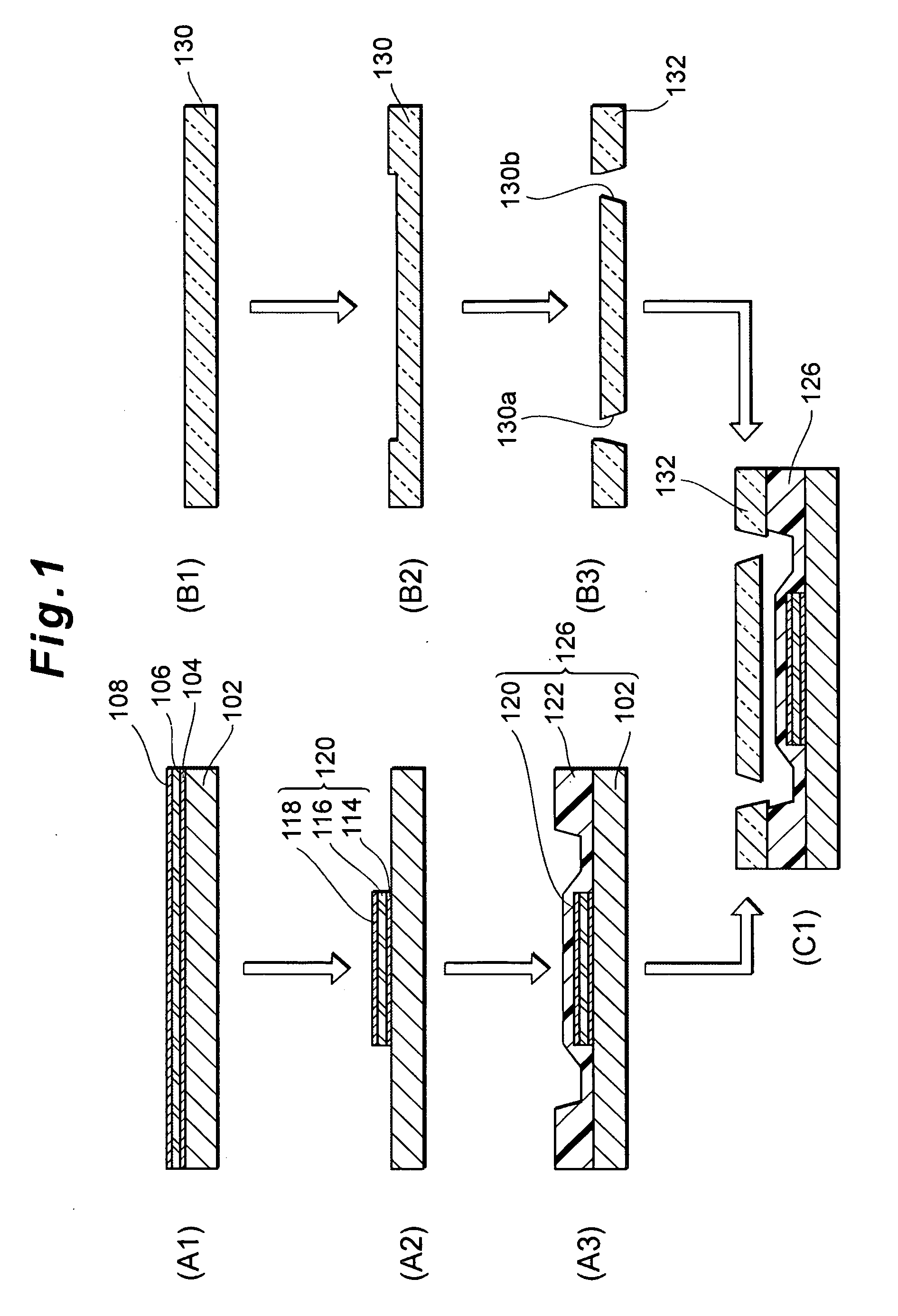
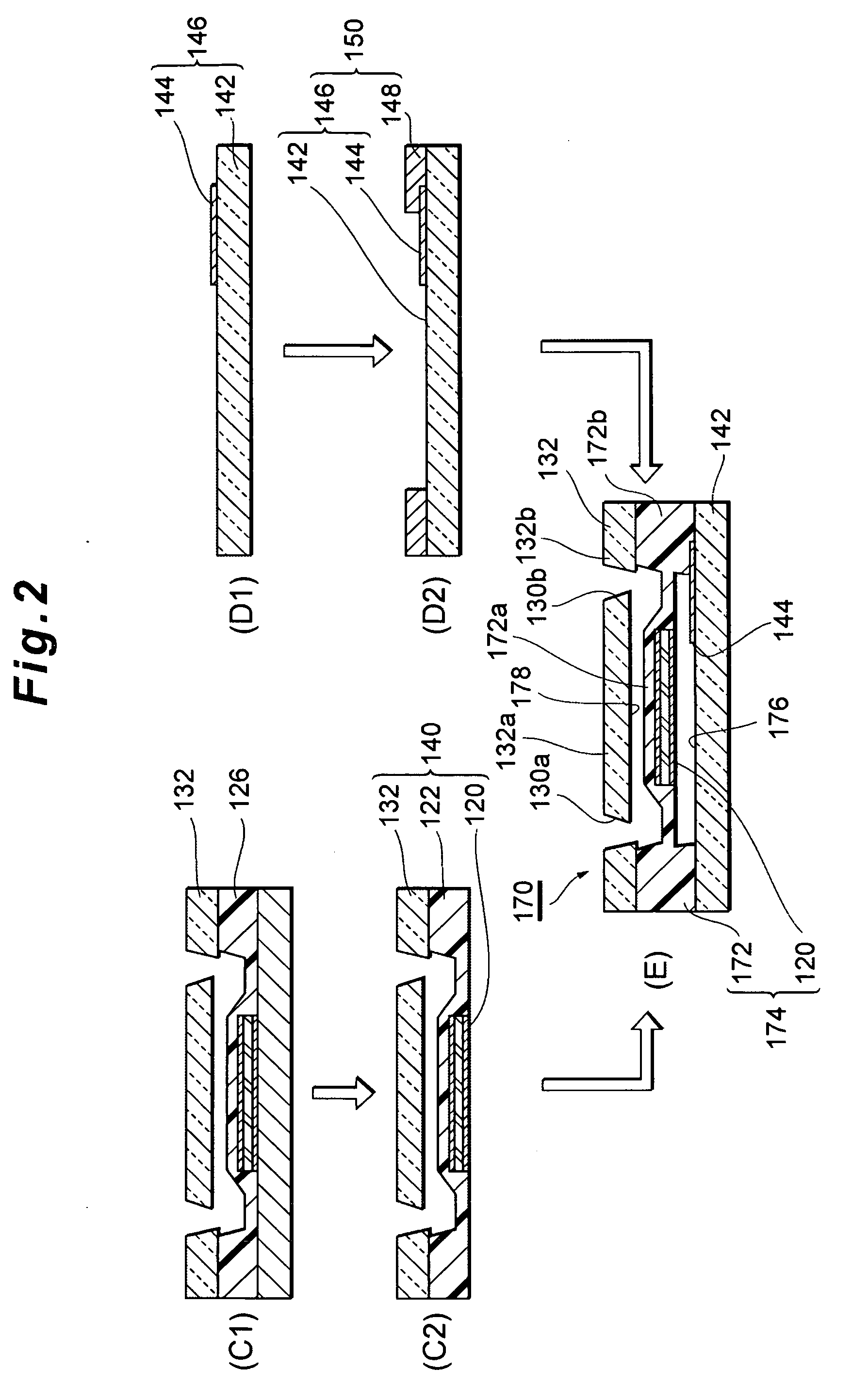
[0026]Here, the motion of the above-mentioned structure in the piezoelectric pump is more stable when both sides are fixed by sandwiching rather than when only one side (for example, the second substrate side in the present invention) is fixed, because the part that functions as the fulcrum of the motion is supported more firmly. In the case of the construction such as the piezoelectric pump according to the present invention, there are the following methods to fix the structure by the first substrate: a method of joining the first substrate to a part of the structure other than an motion part, from a state where nothing is joined to the surface of the structure opposite to the second substrate; and a method of joining the first substrate to the entire surface of the structure opposite to the second substrate and then selectively removing only a part of the first substrate joined to the motion part.
[0027]According to the former method, the first substrate is partially joined to one side of the structure. At this time, the motion part that is not joined to the first substrate is partially relaxed or stretched. As a result, the stress (distribution) in the motion part becomes not uniform, and accordingly a variation in motion arises. Stable fluid transfer is difficult in a piezoelectric pump having such a construction. In a piezoelectric pump having the latter construction according to the present invention, on the other hand, the first substrate is joined to the entire surface of one side of the structure, so that the entire surface of the structure is restrained by the first substrate, and its stress (distribution) is uniform. Subsequently, even when the part of the first substrate joined to the displacement part and the surrounding part which constitute the motion part is removed to expose the motion part, the other parts remain restrained by the joint with the first substrate, and therefore the stress in the motion part is maintained uniform. The piezoelectric pump according to the present invention having such a construction can transfer the fluid with sufficient stability.
[0028]Furthermore, in the piezoelectric pump according to the present invention, not only the displacement part of the piezoelectric element but also the surrounding part of the support member surrounding the displacement part is exposed. Such a motion part is capable of a large motion (in other words, capable of being displaced to a large extent), which contributes to an increase in pump volume.
[0029]Preferably, in the piezoelectric pump according to the present invention, the piezoelectric element includes a first electrode, a piezoelectric body, and a second electrode that are laminated in the stated order in a direction from the first substrate to the second substrate, and a first laminate composed of the first electrode and the piezoelectric body has a smaller product of Young's modulus and thickness than the second electrode. Preferably, in the piezoelectric pump according to the present invention, the piezoelectric element further includes a hard layer on a surface of the second electrode facing the second substrate, and the first laminate has a smaller product of Young's modulus and thickness than a second laminate composed of the second electrode and the hard layer. According to this construction, the motion part of the structure tends to flex more toward the first substrate, while the extent of flex toward the second substrate decreases. This reduces an occurrence of a trouble in the operation of the piezoelectric element, so that the fluid can be transferred more stably.
[0030]Preferably, in the piezoelectric pump according to the present invention, the hard layer is made of at least one metal selected from the group consisting of chromium, tungsten, tantalum, and platinum. These metals are especially high in Young's modulus. Therefore, the fluid can be transferred more stably even when the hard layer is made thin, for the same reason as stated above. Hence this is advantageous for a more compact, thinner piezoelectric pump.
[0031]According to the present invention, it is possible to provide a piezoelectric pump and a fluid transferring system that adequately suppress propagation of a vibration by a piezoelectric element to outside. Moreover, according to the present invention, it is possible to provide a piezoelectric pump that adequately prevents electrodes included in a piezoelectric element from peeling, performs a sufficiently stable operation even in high speed driving, and adequately suppresses a variation in displacement amount. Furthermore, according to the present invention, it is possible to provide a piezoelectric pump that can transfer a fluid with sufficient stability.

Problems solved by technology

Therefore, such high-density integration is difficult.
Besides, in the case of using a component having a poor vibration resistance together with this piezoelectric pump, the component having the poor vibration resistance is still affected by the vibration even when the piezoelectric pump and the component are separated from each other, so that the combined use of the piezoelectric pump and the component is difficult.
Especially when making a compact or thin piezoelectric pump, it is difficult to accurately manufacture a piezoelectric pump that is capable of stable fluid transfer.
In addition, when a plurality of driving electrodes are provided on one piezoelectric element, a stable operation is difficult especially in high speed driving, and a variation in displacement amount tends to occur.
As a result, in the piezoelectric pump as a whole, the voltage applied to the driving electrodes cannot be efficiently converted to the fluid transferring capability of the pump.

Method used


Image

  • Piezoelectric pump and fluid transferring system
  • Piezoelectric pump and fluid transferring system
  • Piezoelectric pump and fluid transferring system

Examples


examples

[0185]The following describes the present invention in more detail by way of examples, though the present invention is not limited to these examples.

[0186](Effect Verification Test Based on Differences in First Substrate Making Method)

[0187]In this test, to verify the displacement amount of the piezoelectric element in the piezoelectric pump, samples shown in FIGS. 15A and 15B were made. First, the making of the sample shown in FIG. 15A according to an example was started by laminating a lower electrode layer (not illustrated, Pt as a material, 0.1 μm in thickness), a piezoelectric body layer (not illustrated, PZT as a material, 2 μm to 2.5 μm in thickness), and an upper electrode layer (not illustrated, Pt as a material, 0.1 μm in thickness) on a Si substrate of 400 μm in thickness by vapor deposition and sputtering, in this order. Next, the lower electrode layer, the piezoelectric body layer, and the upper electrode layer were patterned to a planar shape shown in FIG. 15C by ion m...


PUM


Abstract

To provide a piezoelectric pump including: a structure including a piezoelectric element and a support member that supports the piezoelectric element; and a first substrate and a second substrate that sandwich the structure, wherein the piezoelectric pump has: a pump chamber surrounded by the second substrate and the structure; and a first opening and a second opening that are communicated with the pump chamber, and wherein a space is provided so that the structure flexes in a direction opposite to the pump chamber according to an operation of the piezoelectric element.

Description

FIELD OF THE INVENTION[0001]The present invention relates to a piezoelectric pump and a fluid transferring system.BACKGROUND OF THE INVENTION[0002]Various micropumps for transferring a very small amount of fluid are conventionally studied. A piezoelectric pump that includes a piezoelectric element as an actuator is proposed as one form of such micropumps. For example, Japanese Patent Application Laid-Open No. H10-299659 proposes a piezoelectric pump in which a piezoelectric element is disposed outside a silicon substrate (Si substrate) forming a flow path of a fluid, for the purpose of providing a micropump that can always produce a constant discharge regardless of a change in external pressure and also achieve bidirectional feeding. The document contends that, since this piezoelectric pump uses a unimorph structure of the piezoelectric element and the silicon substrate which functions as a diaphragm, the piezoelectric pump can be manufactured very thin.[0003]Moreover, Japanese Pate...

Claims


Application Information

Patent Timeline
Patent Type & Authority Applications(United States)
IPC IPC(8): F04B43/04
CPCF04B43/046Y10T137/85986F04B43/14
Inventor SHIBATA, MAKOTOWADA, TAKESHIKUMAGAE, MICHIHIRO
Owner TDK CORPARATION
Why Eureka
Try Eureka