
Percussion device

a percussion device and valve technology, applied in the direction of machines/engines, manufacturing tools, portable drilling machines, etc., can solve the problems of reducing efficiency, slow movement of valves from one position to the other, and high final speed of valves in both extreme positions of their movement, so as to improve the efficiency of percussion devices

Active Publication Date: 2010-03-11
SANDVIK MINING & CONSTR OY
View PDF7 Cites 9 Cited by
  • Summary
  • Abstract
  • Description
  • Claims
  • Application Information

AI Technical Summary

Benefits of technology

[0004]The object of the invention is to provide a solution, in which a valve position is made to change faster and more efficiently, and correspondingly, an efficient damping cushion solution will be provided for a percussion piston and a valve.
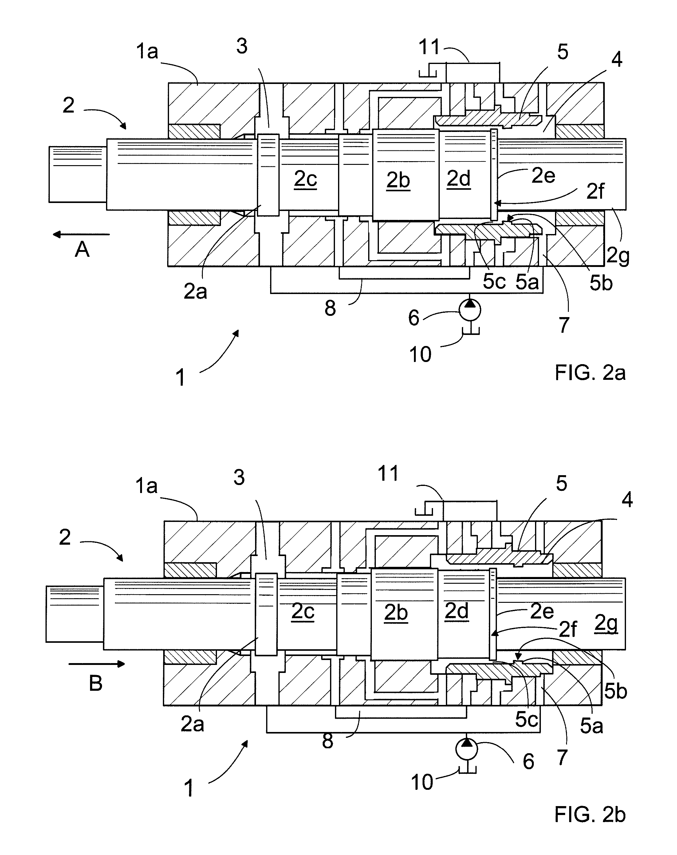
[0007]that the percussion piston having shifted rearwardly to a predetermined position the annular surface in its rear end will be in alignment with the annular surface on the inner surface of the control valve, and consequently as the reverse stroke of the percussion piston continues the pressure in the second pressure fluid space rises decelerating the reverse stroke of the percussion piston and at the same time as pressure is acting on the surfaces on the side of the second pressure fluid space of the control valve it makes the control valve move towards the front end of the percussion device, whereby shoulders of the percussion piston and of the control valve will move apart so that the pressure fluid in the front end of the control valve will be able to flow into the second pressure fluid space in the rear end of the percussion piston and the control valve closes the pressure fluid flow through the channel out of the percussion device.
[0009]The solution of the invention has an advantage that the efficiency of the percussion device improves, because as a result of the control valve movement the pressure fluid in front thereof is able to move between a groove in the percussion piston and a protrusion in the control valve into the rearmost pressure fluid space of the percussion device, i.e. into a work space, and it is not made to flow into the pressure fluid container. Further, the valve speed is damped without a separate damping cushion.

Problems solved by technology

The external pressure control poses a problem that the valve moves slowly from one position to another.
In the forced control solution, in turn, the position change of the valve is fast, but a problem is that the valve has a high final speed in both extreme positions of its movement.
In addition, the pressure fluid in front of the valve flows directly into a tank, which decreases efficiency.

Method used


Image

  • Percussion device
  • Percussion device
  • Percussion device

Examples


Embodiment Construction

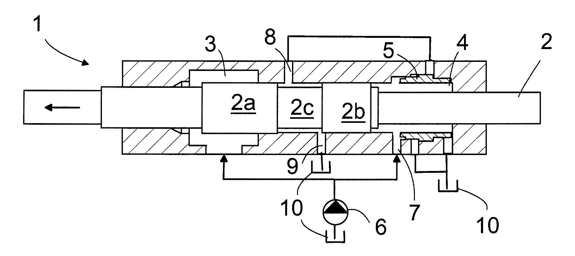
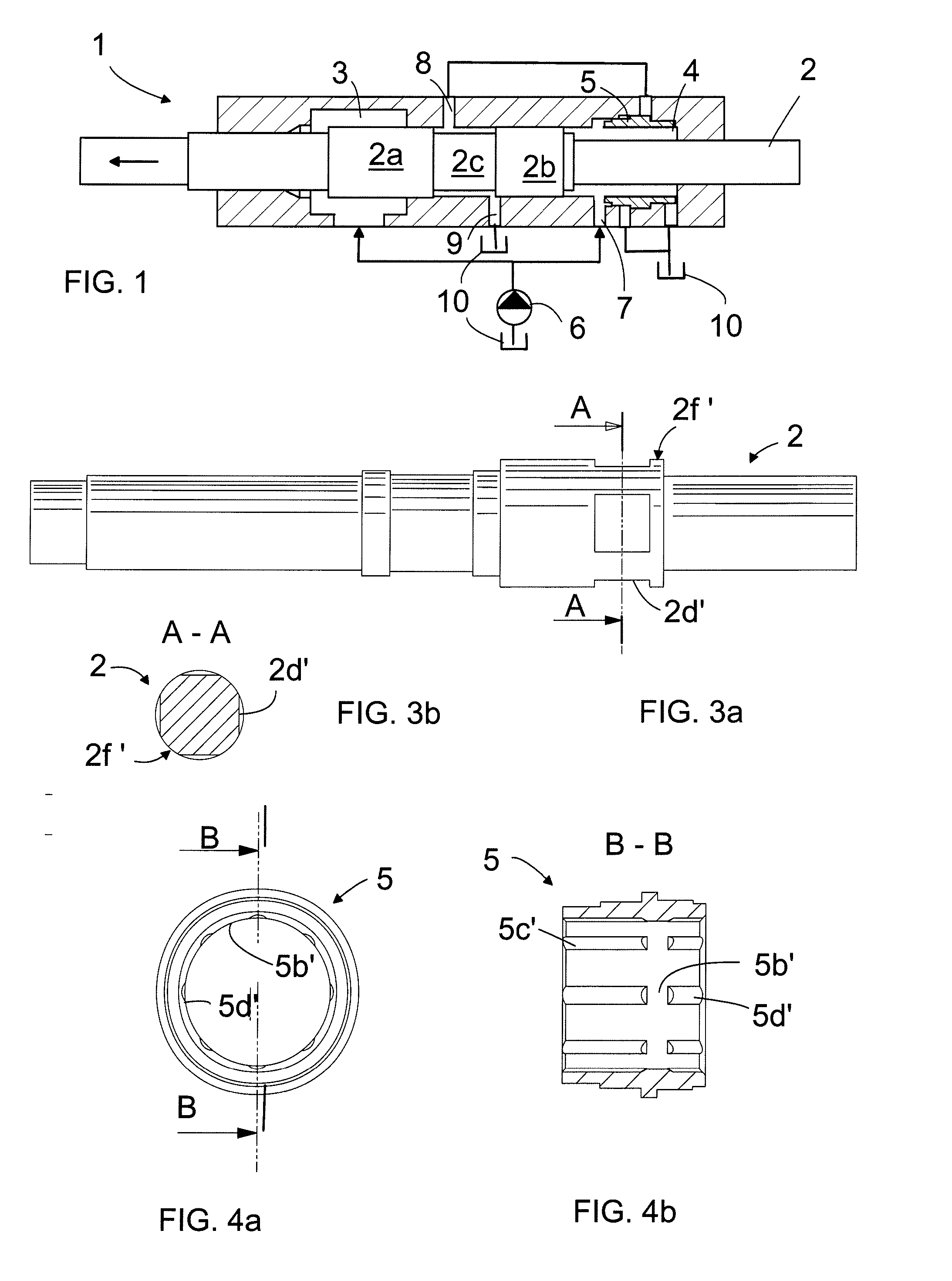
[0015]FIG. 1 shows schematically a known percussion device solution. It comprises a percussion device 1, inside which a percussion piston 2 moves in a reciprocating manner. The percussion piston 2 comprises shoulders 2a and 2b and between them there is an annular groove 2c, by means of which the operation of the percussion device is controlled. In the front end of the percussion device there is a first pressure fluid space 3 and in the rear end a second pressure fluid space 4. Inside the pressure fluid space 4 there is a control valve 5 axially to the percussion piston. Pressure fluid is fed from a pressure fluid pump 6 to the first pressure fluid space 3 of the percussion device continuously and to the second pressure fluid space via a channel 7, controlled by the control valve 5, periodically. In the percussion device body there is also a second pressure fluid channel 8 and a third pressure fluid channel 9, which is communicating with a pressure fluid container 10. The second pres...


PUM

PropertyMeasurementUnit
Pressureaaaaaaaaaa
Flow rateaaaaaaaaaa
Diameteraaaaaaaaaa

Abstract

The invention relates to a percussion device having a body and a percussion piston moving therein, pressure fluid spaces in the rear and front ends of the percussion piston and pressure fluid channels for feeding pressure fluid into the percussion device. The percussion piston and the control valve comprise surfaces, which, when aligned, substantially close the pressure fluid flow from the pressure fluid space locating behind the percussion piston in front of the control valve, whereby the produced pressure displaces the control valve to another position.

Description

BACKGROUND OF THE INVENTION[0001]The invention relates to a percussion device comprising a body and therein a percussion piston that moves longitudinally in a reciprocating manner by action of pressure fluid, in the body a first and a second pressure fluid space in the rear end and correspondingly in the front end of the percussion piston and a control valve that is substantially sleeve-like, locating around the rear end of the percussion piston and movably mounted in the longitudinal direction of the percussion piston, as well as pressure fluid channels for feeding pressurized pressure fluid in and out of the percussion device.[0002]In pressure-fluid-operated percussion devices the reciprocating percussion movement of the percussion piston is controlled by a control valve that controls pressure fluid feed onto pressure surfaces of the percussion piston. In a known solution the control valve is located axially to the percussion piston in the rear end of the percussion piston. The po...

Claims


Application Information

Patent Timeline
IPC IPC(8): B25D9/20F01L15/00
CPCB25D9/20B25D9/18B25D17/245F15B15/22E21B1/32
Inventor KOSKIMAKI, ANTTIKOTALA, ARI
Owner SANDVIK MINING & CONSTR OY
Learn More