
Chromatography Membranes, Devices Containing Them, and Methods of Use Thereof

a technology of chromatography membrane and ion exchanger, which is applied in the direction of cation exchanger, amphoteric ion exchanger, complex ion exchanger, etc., can solve the problems of significant downtime for a filter change, high-purity lysozyme recovery is extremely laborious and costly, and the filter is not fully plugged

Inactive Publication Date: 2010-03-11
NATRIX SEPARATIONS
View PDF101 Cites 34 Cited by
  • Summary
  • Abstract
  • Description
  • Claims
  • Application Information

AI Technical Summary

Benefits of technology

[0026]wherein said macropores of said macroporous cross-lin

Problems solved by technology

Due to the viscous, highly concentrated nature of egg white, and the nature of the other protein constituents, recovering high-purity lysozyme in good yield is extremely laborious and costly.
The flow field moves the flocs onto the surface and into the bulk of the filter medium, ultimately resulting in plugging of the filter.
In practice, a plugged filter may cause a significant amount of downtime for a filter change.
A raw or semi-conditioned process stream that contains high-value materials is often highly viscous or highly contaminated.
As such, DFF separation approaches are difficult or challenging due to blinding of the membrane with the solute present in the feed stream.
Additionally, these processes often require high pressure to maintain a reasonable flux of permeate.
However, only a relatively small amount of permeate is collected during each retentate volume-pass, and thus a significant processing time is typically associated with TFF procedures.
However, filtration devices tend to clog when used over an extended period of time and must be timely replaced.
Clogging of a filtration device occurs: (1) when the membrane pores become obstructed, typically with trapped cells, particulate matter, cell debris or the like, or (2) when the feed channel (into a TFF device) becomes obstructed by solids or colloidal material and / or cell debris.
This clogging of the feed channel or membrane pores results in a decreased liquid flow across the porous filter membrane.
The result is a change in system pressure which, if not properly addressed, runs the risk of serious detriment to the operation which incorporates the filtration procedure.
The devices may or may not have flexible screens in the feed channels to support the membranes.
Despite the apparent advantages of using a system such as this, the cost tends to be high.

Method used


Image

  • Chromatography Membranes, Devices Containing Them, and Methods of Use Thereof
  • Chromatography Membranes, Devices Containing Them, and Methods of Use Thereof
  • Chromatography Membranes, Devices Containing Them, and Methods of Use Thereof

Examples


example 1

Dead-End versus Cross-Flow Modes for Viral Capture

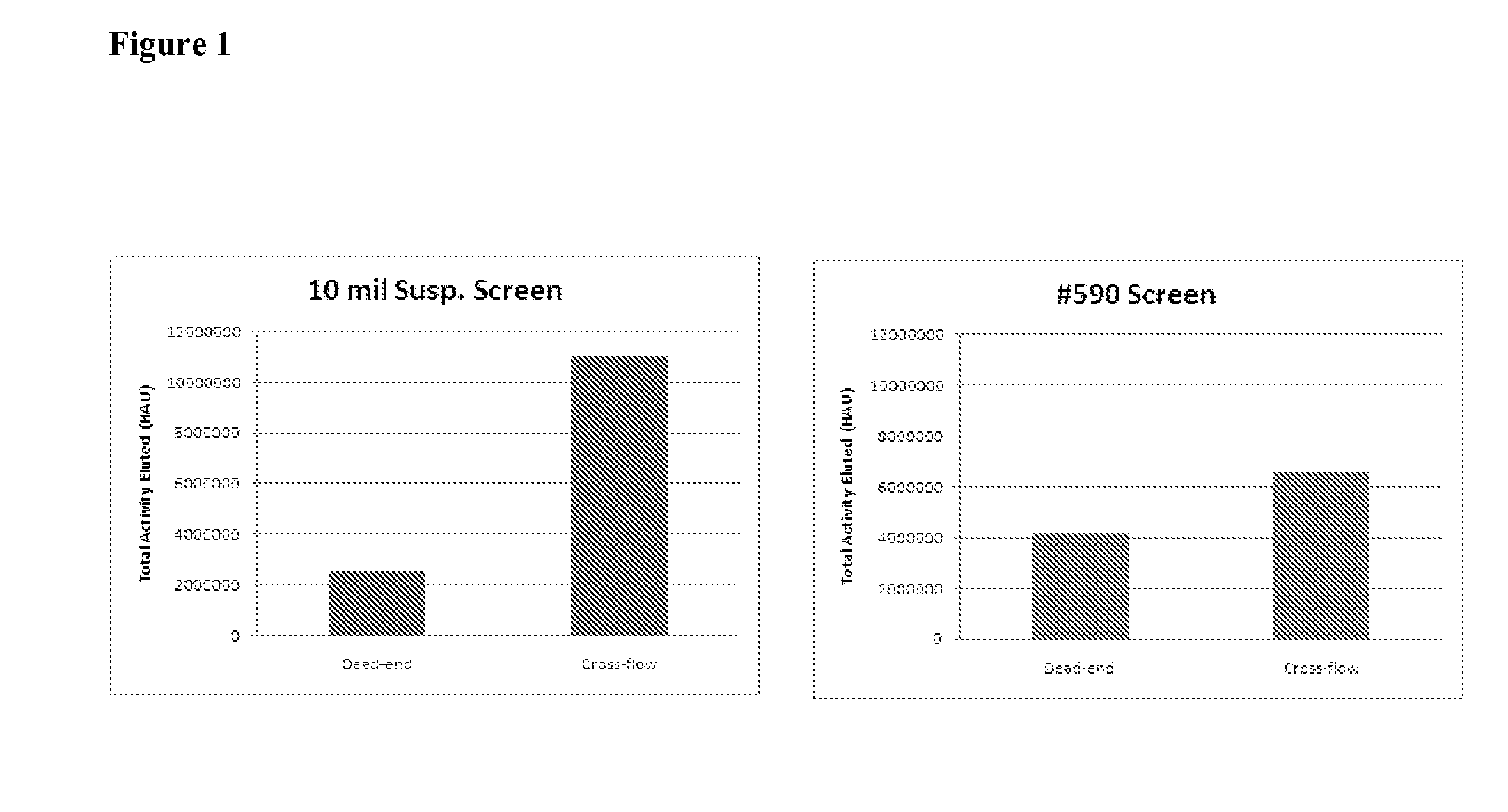
[0309]An example of the improvement of cross-flow technology versus dead-end technology can be realized when the two modes are compared directly to each other. FIG. 1 shows two experiments in which a specific device was run as a dead-end and as cross-flow device. The material of interest is a virus. In both cases, the capture of the cross-flow device exceeded the dead-end version, as indicated by the amount to the pure target material capture after washing and elution.

example 2

Chromatographic Capture and Harvest: Elution of Ovalbumin and Lysozyme

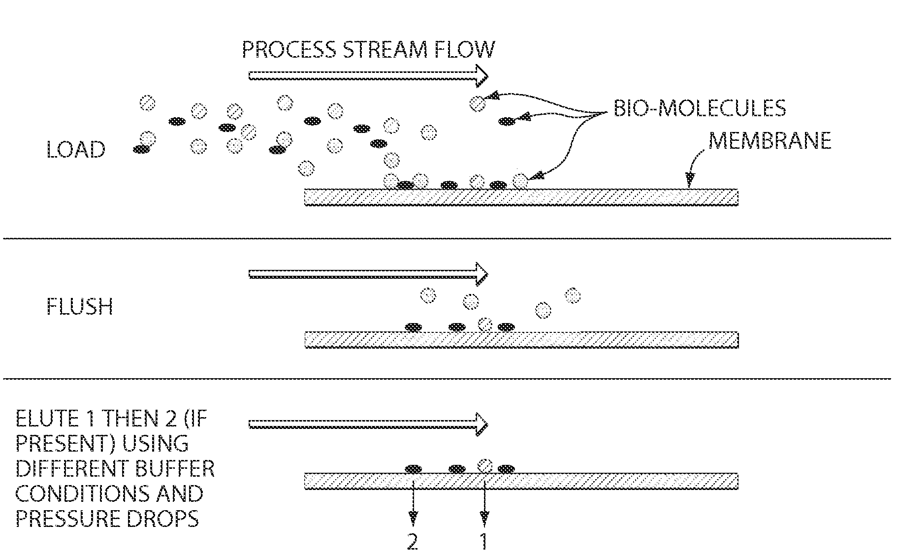
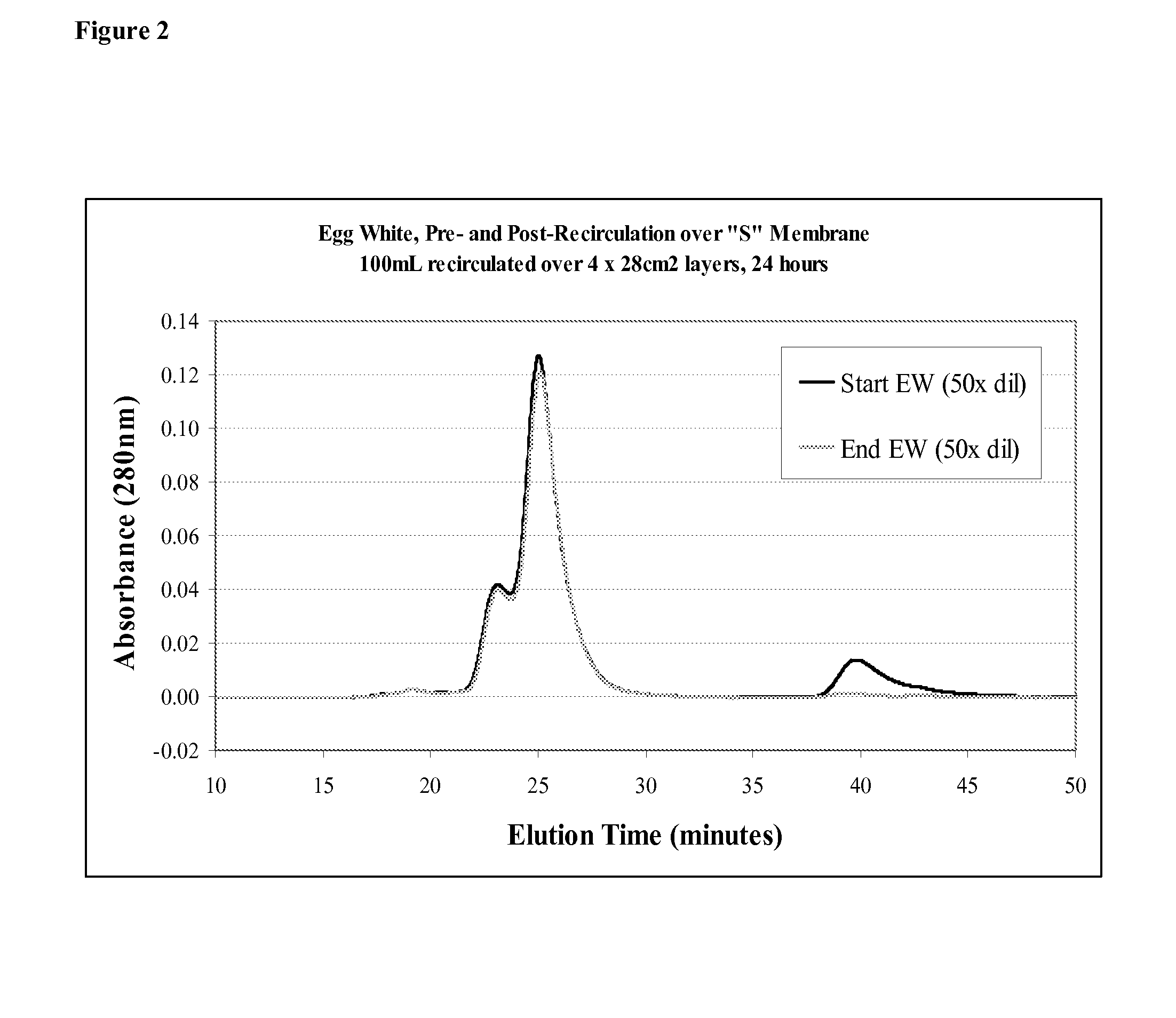
[0310]The membrane can selectively adsorb two protein materials from the feed stream and then, through the use of an altering buffer fluid, selectively elute the target bio-molecules. FIGS. 2 and 3 illustrate this effect. The initial feed stream of egg white was exposed to a membrane surface in cross-flow mode. Once the feed stream was removed and the membrane washed, both Ovalbumin and lysozyme were found adhered to the membrane (FIG. 2). Under specific buffer conditions, the proteins were selectively eluted (FIG. 3), which demonstrates the chromatographic nature of the membrane in cross-flow mode.

example 3

Orthogonal Two-Step Capture and Harvest

[0311]See FIG. 4.


PUM

PropertyMeasurementUnit
Diameteraaaaaaaaaa
Diameteraaaaaaaaaa
Sizeaaaaaaaaaa

Abstract

Described herein are fluid treatment devices for use in tangential flow filtration, comprising a housing unit and a composite material, wherein the composite material comprises: a support member comprising a plurality of pores extending through the support member; and a non-self-supporting macroporous cross-linked gel comprising macropores having an average size of 10 nm to 3000 nm, said macroporous gel being located in the pores of the support member. The invention also relates to a method of separating a substance from a fluid, comprising the step of placing the fluid in contact with an inventive device, thereby adsorbing or absorbing the substance to the composite material contained therein.

Description

RELATED APPLICATIONS[0001]This application claims the benefit of priority to U.S. Provisional Patent Application Ser. No. 61 / 093,600, filed Sep. 2, 2008; and U.S. Provisional Patent Application Ser. No. 61 / 102,797, filed Oct. 3, 2008; both of which are hereby incorporated by reference in their entirety.BACKGROUND OF THE INVENTION[0002]Membrane-based water treatment processes were first introduced in the 1970s. Since then, membrane-based separation technologies have been utilized in a number of other industries. In the pharmaceutical and biotechnology industries, the use of preparative chromatography, direct flow filtration (DFF) and tangential flow filtration (TFF), including micro-, ultra-, nano-filtration and diafiltration are well-established methods for the separation of dissolved molecules or suspended particulates. Ultrafiltration (UF) and microfiltration (MF) membranes have become essential to separation and purification in the manufacture of biomolecules. Biomolecular manufa...

Claims


Application Information

Patent Timeline
IPC IPC(8): B01D15/38B01D35/30C02F1/42B01J49/00B01D15/36
CPCB01D63/082B01D63/087B01D69/10B01L3/502753B01L9/527B01L2200/0647B01D63/14B01L2300/0803B01L2300/0816B01L2300/0887B01L2400/0409B01D63/02B01D63/10B01L2300/0681C12N9/2462C12Y302/01017B01D63/005B01D69/12B01D71/00C07K1/22B01D63/024B01D69/02C07K14/77C07K16/00B01D2315/10B01D2325/36B01D63/034B01D69/106
Inventor BRELLISFORD, DAMIANCROSSLEY, DONNA L.MCLNTOSH, GREGRUMAN, ROBERTRYDALL, JOHNSHIELDS, CHRISTOPHER S.
Owner NATRIX SEPARATIONS
Learn More