Tomography arrangement and method for monitoring persons

a technology for monitoring persons and tomography, applied in the field of tomography arrangement, can solve the problems of inability to adapt the viewing range of the camera to the patient positioning, the additional assembly effort of the camera onto the wall, and the known video camera system, etc., to achieve the widest and deepest coverage of video recording

Inactive Publication Date: 2010-03-11
SIEMENS HEATHCARE GMBH
View PDF7 Cites 41 Cited by
  • Summary
  • Abstract
  • Description
  • Claims
  • Application Information

AI Technical Summary

Benefits of technology

[0033]The first video camera and/or the second video camera are particularly preferably directly attached in a housing of the tomography arrangement to an input region and/or output region of the measuring chamber, in a particularly advantageous fashion to the upper region of the measuring chamber. This produces the best recording angle and/or the widest and deepest coverage of the video recording. It is also advantageous that no additional attachment apparatus is needed for the respective camera, but instead that this is directly positioned where a patient can best be monitored.
[0034]An advantageous development of this embodiment provides for a first and/or a second video camera to be attached at least to two ends of the measuring chamber. A first and a second video camera are particularly preferably attached to both ends of the measuring chamber. A first and a second video camera may however also be attached to only one end of the measuring chamber and only one of the two video cameras may be attached to the other end. A “minimal version” of the development provides for only one video camera to be provided on one end of the measuring chamber in each instance, in other words either a first video camera on one end or a second video camera on the other end or two first video cameras or two second video cameras on

Problems solved by technology

A few disadvantages result with the known video camera systems however.
For instance, the camera viewing range cannot be adapted as a function of the patient positioning.
One further problem consists in the additional assembly effort of the camera onto the wall.
Furthermore, when assembling the camera onto the magnet casing, the region in front of the measuring chamber is itself restricted by the camera and is thus only accessible for an operator with limitat

Method used


Image

  • Tomography arrangement and method for monitoring persons
  • Tomography arrangement and method for monitoring persons
  • Tomography arrangement and method for monitoring persons

Examples


Embodiment Construction

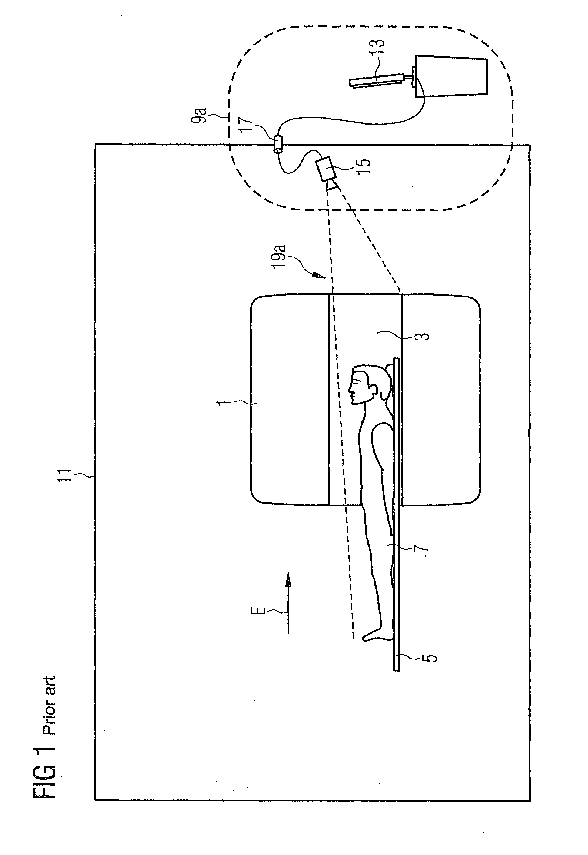
[0047]FIG. 1 shows a tomography arrangement 1, here a magnetic resonance tomograph, according to the prior art. It is in an examination room 11 and essentially consists of a tube, which forms a measuring chamber 3, in which a patient couch 5 is arranged, upon which a patient 7 can be introduced into the measuring chamber 3 in the insertion direction E. It also has a monitoring facility 9a. This consists of an image output unit 13 outside the examination room 11, here a computer terminal, and a video camera 15 assembled on a wall of the examination room 11, said video camera being connected to the image output unit 13 by way of optical cables and a feedthrough waveguide 17. The video camera 15 is focused on the measuring chamber 3 and operates in the visible light wave range. With an optimal alignment of the video camera 15, a patient 7 can be recorded in a recording angle range 19a and his / her movements can be identified on the image output unit 13. The further the video camera 15 i...


PUM


Abstract

The invention relates to a tomography arrangement with a tubular measuring chamber and a monitoring facility. This monitoring facility includes at least one first video camera focusing on the measuring chamber and at least partially optically recording the same, said first video camera operating in the non-visible light wave range, in order to record moving images and an image output unit for outputting the moving images as well as a first illumination facility focusing on the measuring chamber, which, during operation, illuminates the measuring chamber in the same light wave region, in which light wave range the first video camera operates. The invention also relates to a method for monitoring persons.

Description

CROSS REFERENCE TO RELATED APPLICATIONS[0001]This application claims priority of German application No. 10 2008 046 023.0 filed Sep. 5, 2008, which is incorporated by reference herein in its entirety.FIELD OF THE INVENTION[0002]The present invention relates to a tomography arrangement with a tubular measuring chamber, into which persons can be introduced for an examination, and a monitoring facility focusing on the measuring chamber and at least partially optically recording the same in order to record moving images. The monitoring facility is used both to record the current well-being of the patient as well as to detect possible movements of the patient during the imaging. It also relates to a method for monitoring persons in a tubular measuring chamber of a tomography system.BACKGROUND OF THE INVENTION[0003]Within the framework of imaging methods such as magnetic resonance tomography (MR), computed tomography (CT), positron-emission tomography (PET) or single-proton-emission compu...

Claims


Application Information

Patent Timeline
IPC IPC(8): G01T1/161G01J5/00
CPCA61B5/0555A61B6/08H04N7/181H04N5/2256G01R33/283A61B5/055H04N23/56
Inventor ALBRECHT, HERBERT
Owner SIEMENS HEATHCARE GMBH
Why Eureka
Try Eureka