Level sensing device

a level sensing and level technology, applied in the direction of liquid/fluent solid measurement, instruments, using reradiation, etc., can solve the problems of time-consuming and expensive manufacture, high construction cost, and complicated manufacturing issues

Active Publication Date: 2010-03-11
SIEMENS AG
View PDF23 Cites 39 Cited by
  • Summary
  • Abstract
  • Description
  • Claims
  • Application Information

AI Technical Summary

Benefits of technology

[0017]This can be helpful to determine how soon a silo e.g. on a production line for concrete st

Problems solved by technology

For radars operating at high frequencies (HF) using monolithic microwave integrated circuits (MMICs) packaged as bare die, construction costs have traditionally been high.
In addition, the transition to the antenna has required complex precision construction and the MMICs are delicate components requiring protection which further complicates the issue of manufacture.
Antenna connections are frequently made using precision transitions to waveguide, which can be time consuming and expensive to man

Method used


Image

  • Level sensing device
  • Level sensing device
  • Level sensing device

Examples


Embodiment Construction

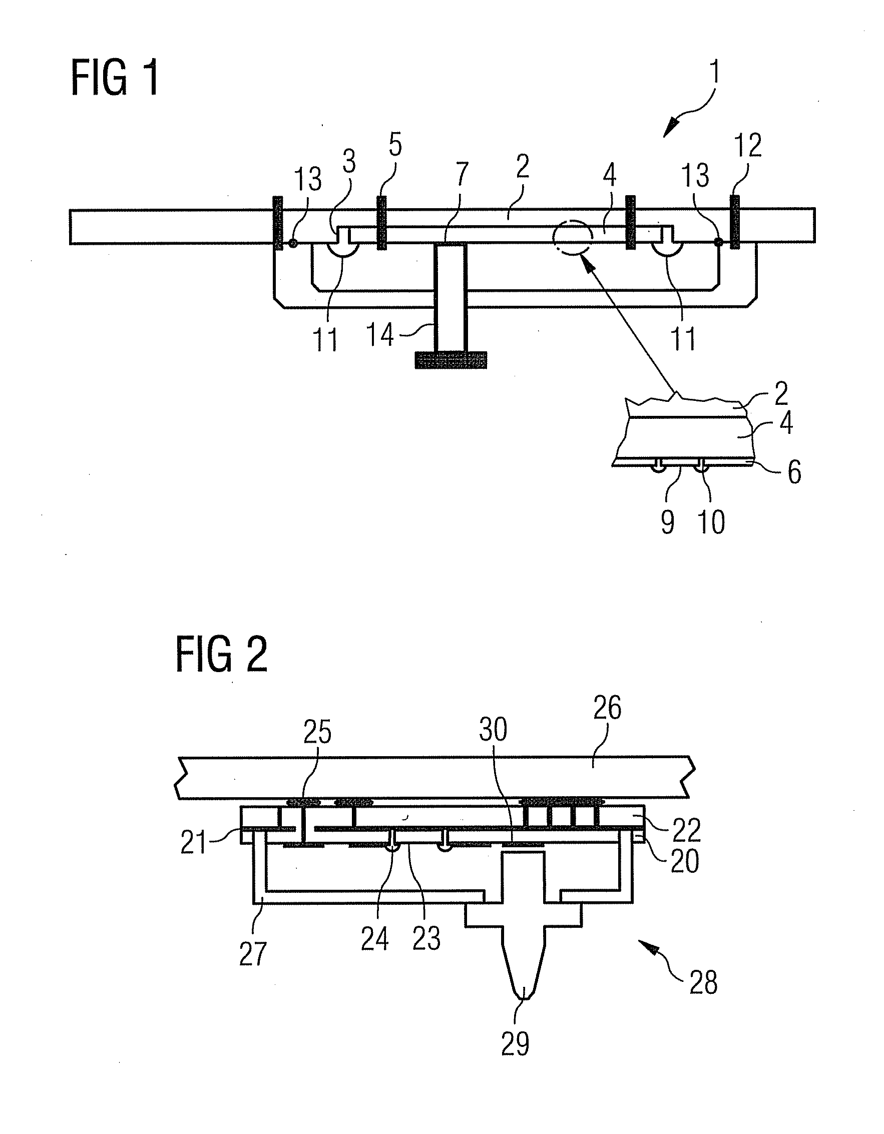
[0025]FIG. 1 illustrates a conventional construction of a radar module 1. A radar technology printed circuit board (PCB) 2 is provided with a recess 3 into which a radio frequency (RF) substrate 4 is located and fitted by locating pins, or fixings 5. A waveguide transition 7 is provided on a high frequency module which is illustrated in more detail in the exploded section of FIG. 1. The RF substrate, or metal backing 4 contacts a ground plane of the PCB 2. Dielectric and MMIC components 6, 9 are provided on the RF substrate 4 and joined via bondwires 10. The HF module is also electrically joined to the PCB via bondwires 11. In order to protect the HF module and its connection to the PCB, a casing is provided which is located by pins, or fixings 12 and sealed by seals 13. Conventionally, the output of the waveguide transition 7 is coupled into a waveguide 14 to exit the module.

[0026]The present invention solves the construction problems of the conventional device by packaging the MMI...


PUM


Abstract

A level sensing device with a high frequency radar system is provided. The radar system includes a radar high frequency module, a carrier board and a controller. The radar high frequency module is mounted on the carrier board using surface mount techniques. The controller includes a processor and the radar high frequency module has a plurality of components including one or more microwave integrated circuits, a radiating patch antenna, and coupling means for channeling a radiated signal from the patch antenna out of the module. The components are encapsulated to form the module and the coupling means includes a dielectric rod.

Description

CROSS REFERENCE TO RELATED APPLICATIONS[0001]This application is the US National Stage of International Application No. PCT / GB2008 / 050161 filed Mar. 7, 2008 and claims the benefit thereof. The International Application claims the benefits of Great Britain Application No. 0705449.7 GB filed Mar. 22, 2007; both of the applications are incorporated by reference herein in their entirety.FIELD OF INVENTION[0002]This invention relates to a level sensing device using a high frequency radar system, in particular for range finding and level sensing of bulk materials, or fluids.SUMMARY OF INVENTION[0003]For radars operating at high frequencies (HF) using monolithic microwave integrated circuits (MMICs) packaged as bare die, construction costs have traditionally been high. In addition, the transition to the antenna has required complex precision construction and the MMICs are delicate components requiring protection which further complicates the issue of manufacture. Conventionally, modules wi...

Claims


Application Information

Patent Timeline
IPC IPC(8): G01S13/08
CPCG01F1/002G01F23/284H01Q13/24H01Q1/225H01Q9/0407G01S7/032
Inventor GARROD, ADRIAN GEORGEMOORE, KATHERINESHERRY, DAVID
Owner SIEMENS AG
Why Eureka
Try Eureka