
Measuring a hollow space by means of cylindrically symmetrical triangulation

Inactive Publication Date: 2010-03-11
SIEMENS AG
View PDF10 Cites 27 Cited by
  • Summary
  • Abstract
  • Description
  • Claims
  • Application Information

AI Technical Summary

Benefits of technology

[0007]An object of the invention is to specify an optical measuring device and a method for the three-dimensional measurement of a hollow space which is formed in an object, wherein said device and method allow a measurement of the hollow space which is both particularly rapid and particularly accurate.

Problems solved by technology

In addition, it is functionally important for the gap between the ear and the hearing device to be as small as possible, since background noise via this route can otherwise impair the effect of the hearing device.
At present, determining the shape data is relatively unpleasant for the patient.
However, the shape-impression method has the disadvantage that shrinkage of the plastic material is unavoidable, since the patient cannot be expected to bear the relatively unpleasant procedure involved in producing the shape impression over an extended period of time.
The shape-impression method also has the disadvantage that the ear canal is not measured directly, but is only measured indirectly by measuring the shape impression.
This results in inaccuracies in the finished hearing devices and hence to a corresponding reduction in comfort.

Method used


Image

  • Measuring a hollow space by means of cylindrically symmetrical triangulation
  • Measuring a hollow space by means of cylindrically symmetrical triangulation
  • Measuring a hollow space by means of cylindrically symmetrical triangulation

Examples


Embodiment Construction

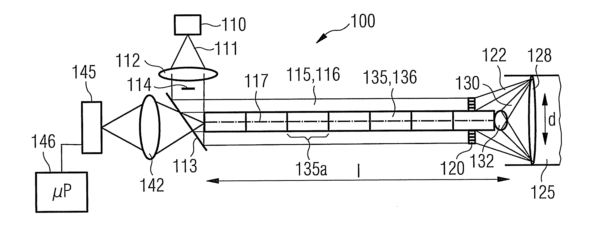
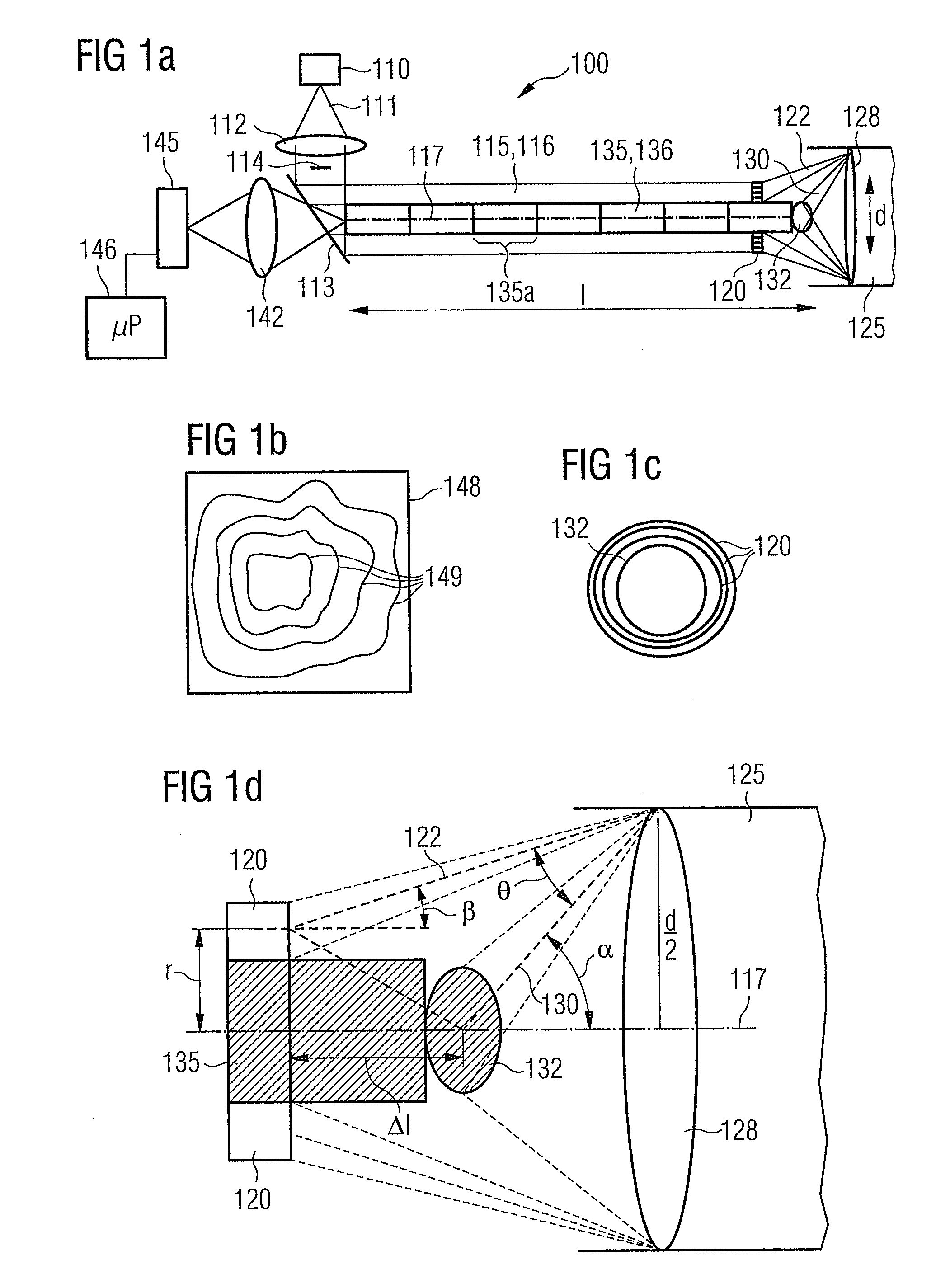
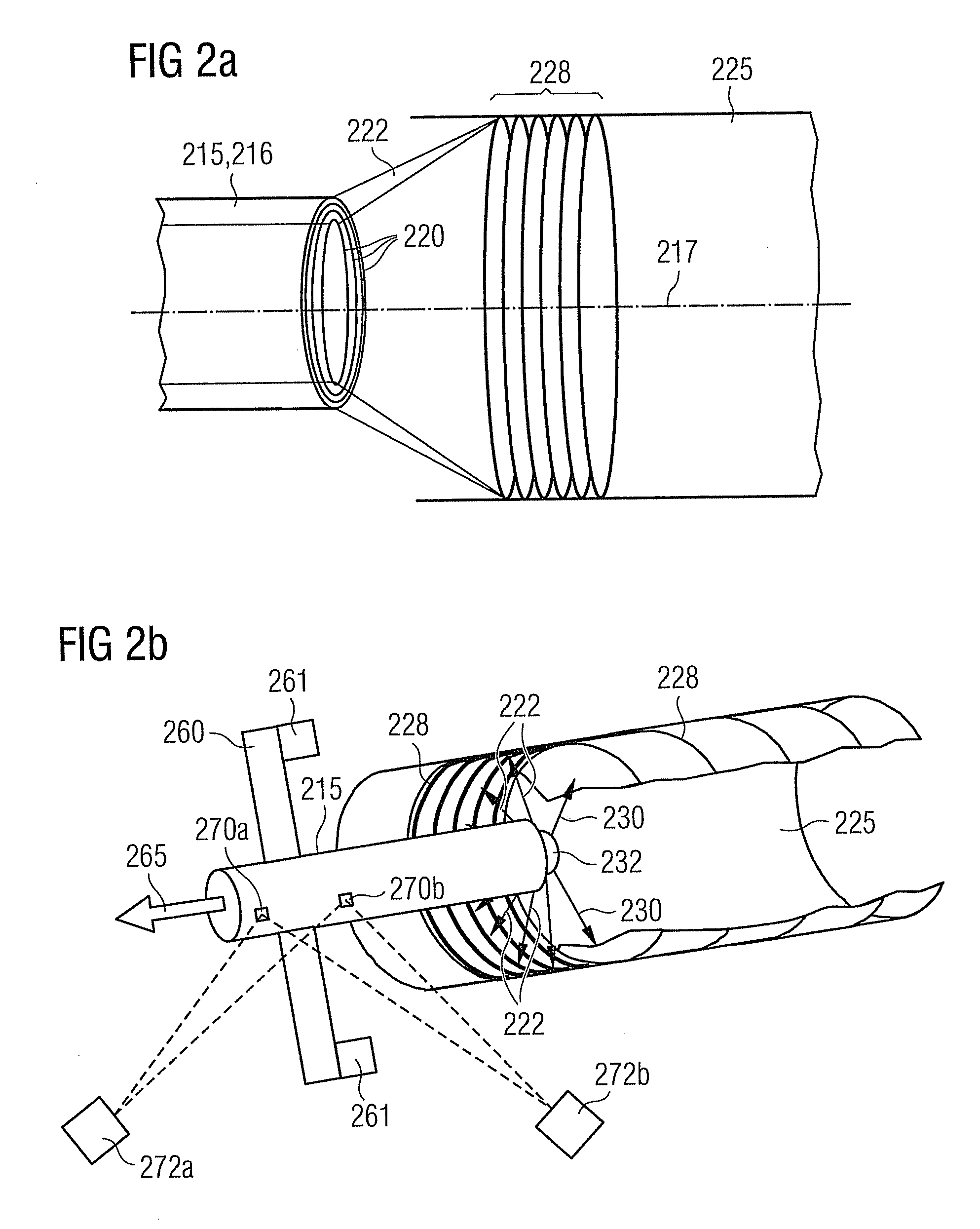
[0071]FIG. 1a shows a cross-sectional view of an optical measuring device 100 as per an exemplary embodiment of the invention. The optical measuring device 100 has a cylindrically symmetrical shape relative to a longitudinal axis 117.

[0072]The optical measuring device 100 features a light source 110, which is a laser diode 110 according to the exemplary embodiment illustrated here. It is obvious that other light sources such as a light-emitting diode, for example, can also be used. The laser diode 110 emits monochromatic illumination light 111, which hits a projection lens system 112 that expands the illumination beam 111. The expanded illumination beam 111 hits a beam splitter 113 which is oriented at an angle of 45° relative to the longitudinal axis 117, such that at least part of the illumination light 111, depending on the reflection capabilities of the beam splitter 113, is input into a hollow cylinder 115 which is arranged symmetrically relative to the longitudinal axis 117. I...


PUM


Abstract

An optical measuring device for a three-dimensional measuring of a hollow space formed within an object is provided. The optical measurement device has a light source, which is provided for emitting illumination light along an illumination beam path, and an optical deflection element, which spatially structures the radiated illumination light such that on an inside wall an illumination line forms, which extends along the longitudinal axis. The shape of the line is dependant on the size and shape of the hollow space. Further, the optical measuring device has a camera, which detects the illumination line via an imaging beam path at a triangulation angle. Through an appropriate evaluation of the image of the detected shape and size of the illumination line by the camera, the three-dimensional shape of the hollow space is determined.

Description

CROSS REFERENCE TO RELATED APPLICATIONS[0001]This application is the US National Stage of International Application No. PCT / EP2007 / 062021 filed Nov. 8, 2007, and claims the benefit thereof. The International Application claims the benefits of German Patent Application No. 10 2006 054 310.6 DE filed Nov. 17, 2006, both of the Applications are incorporated by reference herein in their entirety.FIELD OF INVENTION[0002]The present invention relates to an optical measuring device and to a method for three-dimensional measurement of a hollow space which is formed in an object. In particular, the invention relates to such an optical measuring device and to such a method for the three-dimensional measurement of the auditory canal of a live human or animal.BACKGROUND OF INVENTION[0003]In order to produce custom-fit hearing devices, the shape of the outer and inner auditory canal must be detected and measured precisely. Hearing devices are modeled and adapted with the aid of corresponding thr...

Claims


Application Information

Patent Timeline
IPC IPC(8): H04N15/00G06K9/00
CPCA61B1/042G01B11/25A61B5/1076A61B1/227A61B1/0605
Inventor FORSTER, FRANKLALONI, CLAUDIOROHRLEIN, GERHARDSCHICK, ANTON
Owner SIEMENS AG
Learn More