Eureka AIR delivers breakthrough ideas for toughest innovation challenges, trusted by R&D personnel around the world.

Television Receiver

a receiver and receiver technology, applied in the field of television receivers, can solve the problems of user inability to view the start portion of a desired program, user inability to view the intermediate portion of the program, and considerable time (for several minutes) to complete the cac operation, so as to improve the user-friendliness

Active Publication Date: 2010-03-11
MAXELL HLDG LTD
View PDF6 Cites 21 Cited by
  • Summary
  • Abstract
  • Description
  • Claims
  • Application Information

AI Technical Summary

Benefits of technology

[0018]An object of the present invention is to provide a TV receiver which transmits video data to its monitor unit via wireless transmission by using a channel shared with radar, the TV receiver being capable of preventing the user from missing a program that he wants even when wireless data transmission is interrupted.
[0022]The TV receiver according to the present invention includes a tuner unit and a monitor unit, the tuner unit transmitting program data to the monitor unit via wireless transmission. Even when the start of wireless data transmission is delayed or data transmission is interrupted, the TV receiver can prevent the user from missing the program that the user wants to view, thereby improving the user-friendliness.

Problems solved by technology

In this case, however, it takes considerable time (for several minutes) to complete the CAC operation, determine an unused channel, and become ready for wireless transmission of received images.
During this period, wireless transmission is interrupted and therefore the user cannot view the start portion of a desired program.
This causes a problem that the user cannot view the intermediate portion of the program.
Therefore, when the position of either equipment changes, interference may occur during communication making it necessary to interrupt real-time transmission.
Further, each piece of wireless communication equipment must obtain the installation position information of radar equipment existing in surrounding areas for channel selection, and frequently update it to the latest information, so that the technique is not practical.

Method used


Image

  • Television Receiver
  • Television Receiver
  • Television Receiver

Examples


Embodiment Construction

[0032]An embodiment of the present invention will be explained below with reference to the accompanying drawings.

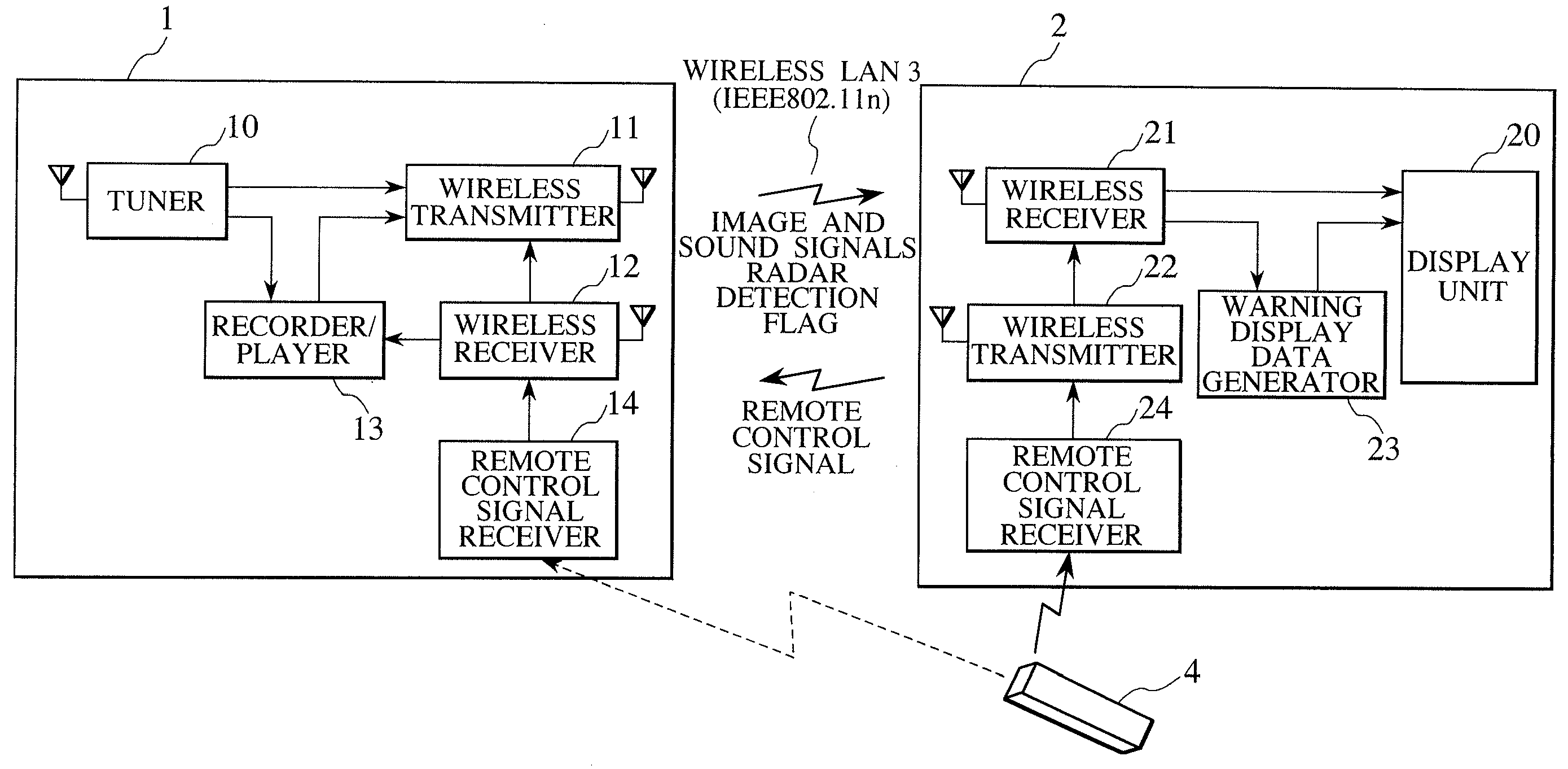
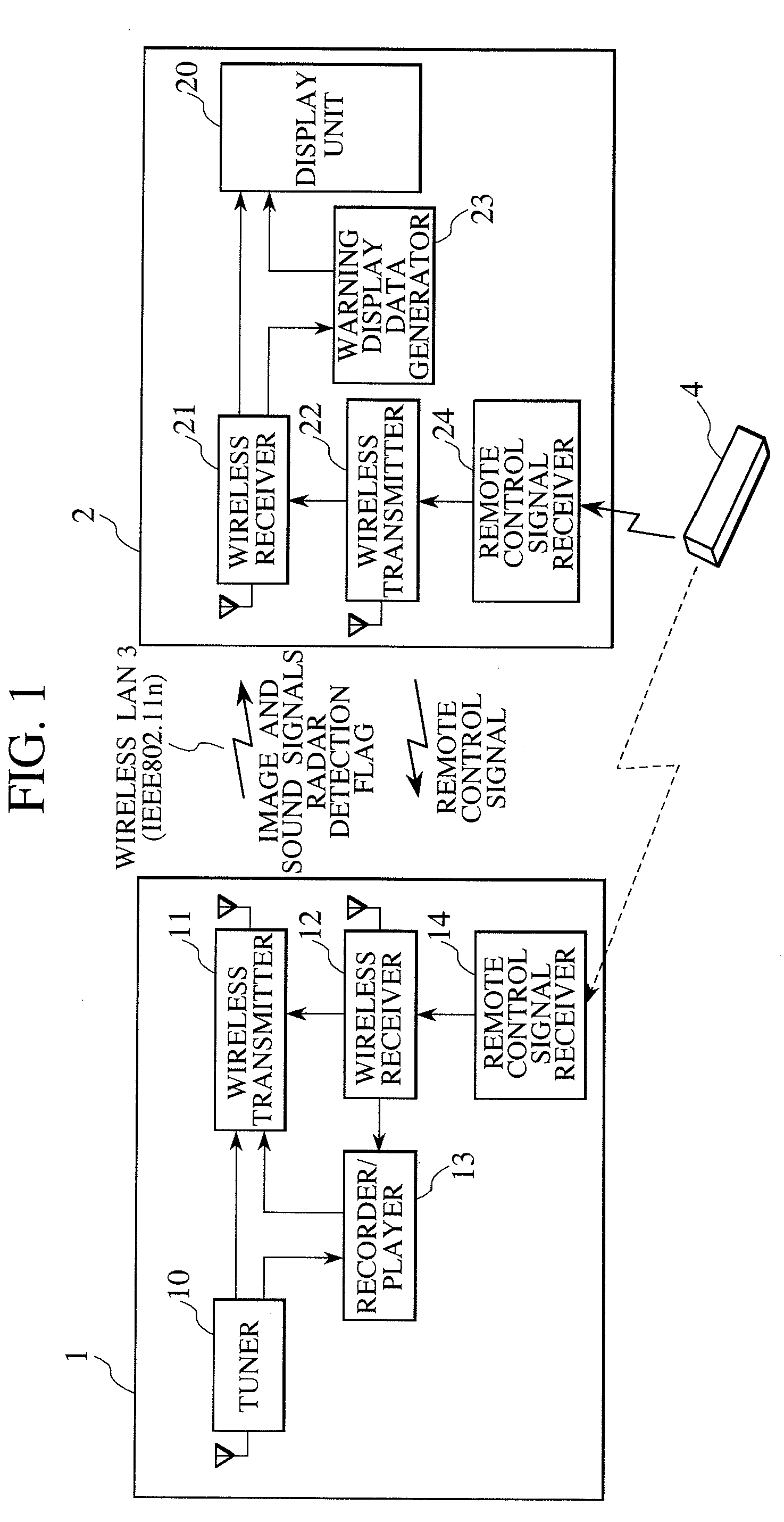
[0033]FIG. 1 shows the schematic configuration of a TV receiver according to an embodiment of the present invention. The TV receiver according to the present embodiment includes a tuner unit 1 which receives a broadcast program and a monitor unit 2 which plays back images and sounds of the program. The tuner unit 1 and the monitor unit 2 are separated from each other. The tuner unit 1 transmits video and audio data to the monitor unit 2 via wireless transmission through a wireless LAN 3. While an operation signal from a remote control 4 is usually received by the monitor unit 2, it is received by the tuner unit 1 when wireless communication by the wireless LAN 3 is interrupted. Further, when communication by the wireless LAN 3 is difficult, it is also possible to connect the tuner unit 1 and the monitor unit 2 with a cable such as HDMI (High Definition Multimedia Interfac...


PUM


Abstract

A TV receiver transmits video data from its tuner unit to its monitor unit via wireless transmission by using a channel shared with radar. When the tuner unit receives a program to be viewed, a recorder / player starts recording of the received program. When wireless transmission of the received program cannot be started on time at the program start time because of detecting an unused channel for wireless transmission, or when a radar wave in the shared channel is detected after starting wireless transmission and then wireless data transmission is interrupted, the recorder / player plays back on a time-shift basis the program recorded on the recording medium, and the program data played back is transmitted to the monitor unit. The TV receiver is capable of preventing the user from missing a program that he wants to view even when wireless data transmission is interrupted.

Description

CLAIM OF PRIORITY[0001]The present application claims priority from Japanese patent application serial No. JP 2008-227861, filed on Sep. 5, 2008, the content of which is hereby incorporated by reference into this application.BACKGROUND OF THE INVENTION[0002]1. Field of the Invention[0003]The present invention relates to a television receiver (TV receiver) in which a tuner unit and a monitor unit are separated from each other, the tuner unit transmitting program data to the monitor unit via wireless transmission.[0004]2. Description of the Related Art[0005]In recent years, high-speed wireless LAN systems conforming to the IEEE802.11n standard, one of wireless networks standard, are coming to be used for information transmission between consumer digital information devices. For example, applying such a wireless LAN to a TV receiver in which a tuner unit and a monitor unit are separated from each other, the tuner unit transmitting program data to the monitor unit, eliminates the need o...

Claims


Application Information

Patent Timeline
IPC IPC(8): H04N5/50H04N5/94G08B5/00H04B1/16H04N5/44H04N5/76H04N5/765H04N7/173
CPCH04H20/08H04N5/44H04N5/775H04N21/4122H04N21/4147H04N21/658H04N21/43637H04N21/44227H04N21/4882H04N21/6377H04N21/4334
Inventor KIMURA, KATSUNOBU
Owner MAXELL HLDG LTD
Why Eureka
Eureka Blog
Learn More