Radio relay apparatus and method

a radio relay and apparatus technology, applied in the field of mobile communication techniques, can solve the problems of affecting the overall system, the error rate and/or capacity performance may be rather degraded, and the signal with a sufficient quality cannot be received, so as to achieve the effect of improving the overall error ra

Inactive Publication Date: 2010-03-11
NTT DOCOMO INC
View PDF2 Cites 44 Cited by
  • Summary
  • Abstract
  • Description
  • Claims
  • Application Information

AI Technical Summary

Benefits of technology

[0011]According to the present invention, an overall error rate can be improved in a radio relay system for transferring signals in accordance with a MIMO scheme.

Problems solved by technology

As a result, if the loop interference is present, signals with a sufficient quality could not be received.
As a result, even if the independently designed weight matrices remove the respective causes of interference, there is a risk that error rate and / or capacity performance may be rather degraded from the viewpoint of the overall system.

Method used


Image

  • Radio relay apparatus and method
  • Radio relay apparatus and method
  • Radio relay apparatus and method

Examples


second embodiment

[0097]The second embodiment of the present invention (F∝I, W≠I) is described below. Portions like the above-mentioned first embodiment are not repeatedly described. In the first embodiment, the feedback type canceling matrix C is optimized at the radio communication apparatus RS20 having a radio relay function. On the other hand, in the second embodiment, the weighting matrix W and the canceling matrix C are jointly optimized. Also in the second embodiment, however, precoding is performed at the radio communication apparatus BS10 having a radio base station function similar to the first embodiment. In other words, the precoding matrix F being equal to √{square root over (Po / M)}·I is used.

(2.1 Radio Relay Apparatus)

[0098]FIG. 5 illustrates an exemplary functional arrangement of the radio communication apparatus RS20 having a radio relay function according to this embodiment. Similar to the first embodiment, the radio communication apparatus RS20 includes receive antennas 21, transmit...

third embodiment

[0115]The third embodiment of the present invention (general F, W=I) is described below. Portions like the first and second embodiments are not repeatedly described. In the first embodiment, the feed-back type canceling matrix C is optimized at the radio communication apparatus RS20 having a radio relay function. In the third embodiment, the canceling matrix C as well as the precoding matrix F is optimized. In the third embodiment, however, the feed-forward type weighting matrix W is not used for weighting operations similar to the first embodiment. It is assumed that W=I.

(3.1 Radio Relay Apparatus)

[0116]FIG. 7 illustrates an exemplary functional arrangement of the radio communication apparatus RS20 according to this embodiment. Similar to the first embodiment, the radio communication apparatus RS20 includes receive antennas 21, transmit antennas 22, a canceling unit 23 for removing loop interference and reducing inter-antenna interference and inter-user interference, an optimal wei...

fourth embodiment

[0133]The fourth embodiment of the present invention (general F, W≠I) is described below. In the fourth embodiment, the precoding matrix F and the weighting matrix W as well as the canceling matrix C are jointly optimized.

(4.1 Radio Relay Apparatus)

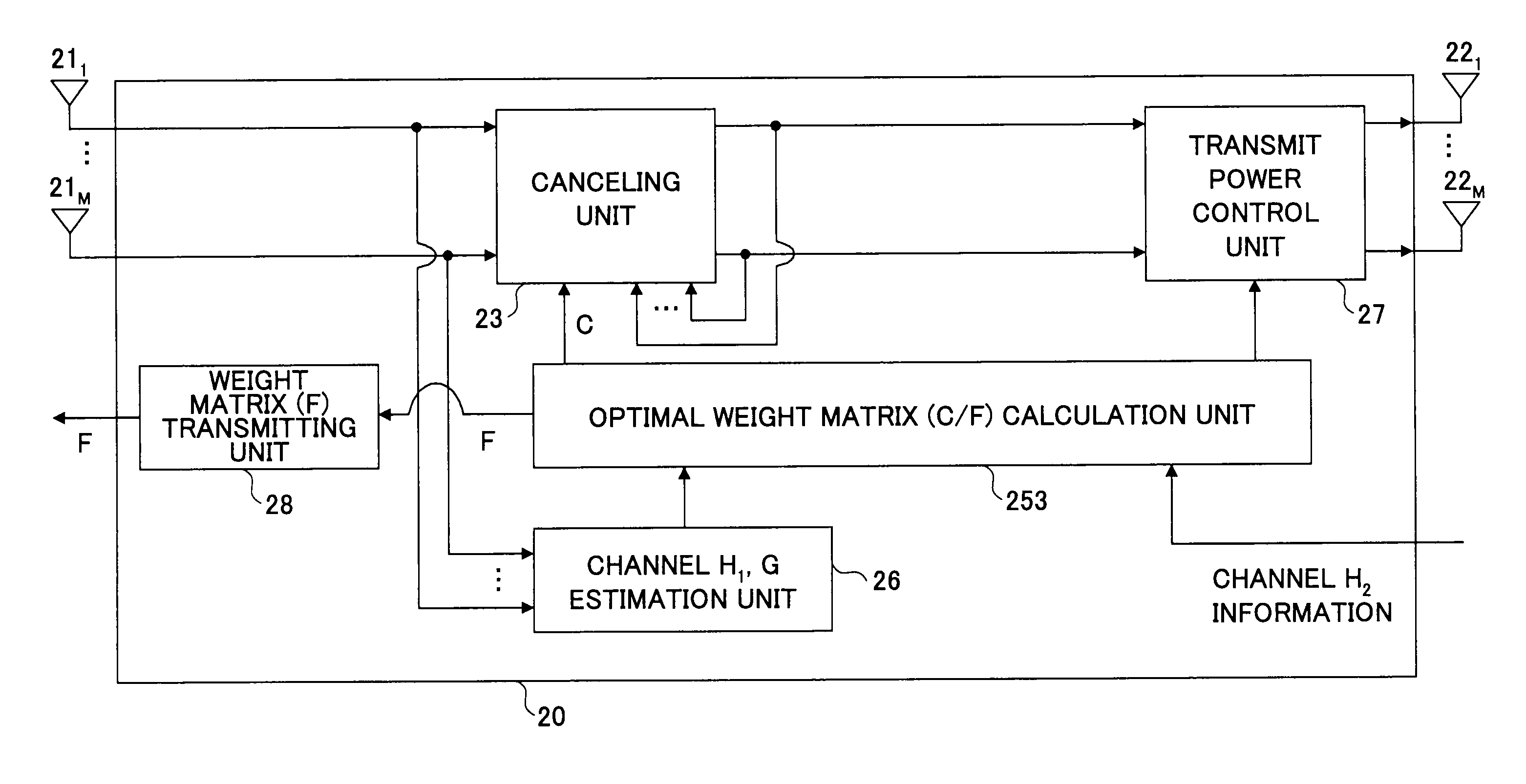
[0134]FIG. 9 illustrates an exemplary arrangement of the radio communication apparatus RS20 having a radio relay function according to this embodiment. Similar to the first embodiment, the radio communication apparatus RS20 includes receive antennas 21, transmit antennas 22, a canceling unit 23 for removing loop interference, an optimal weight matrix calculation unit 254, a channel estimation unit 26 and a transmit power control unit 27. The radio communication apparatus RS20 differs from the first embodiment in that it includes a weighting unit 24 for reducing inter-antenna interference and inter-user interference and a weight matrix transmitting unit 28.

[0135]The receive antennas 21, the transmit antennas 22, the canceling unit 23, the ...


PUM


Abstract

A disclosed radio relay apparatus receives signals from a transmitter via multiple receive antennas and transmits relay signals derived from the received signals to a receiver via multiple transmit antennas. The apparatus includes a channel estimation unit configured to estimate a forward channel matrix H1 representing radio channel characteristics between the transmitter and the radio relay apparatus and a loop channel matrix G representing interference occurring in the relay signals due to concurrently transmitting and receiving signals at the radio relay apparatus, a weight optimization unit configured to derive a canceling matrix C through iterative operations using the forward channel matrix H1, the loop channel matrix G and a backward channel matrix H2 representing radio channel characteristics between the radio relay apparatus and the receiver, and a feedback compensation unit configured to subtract a signal weighted in accordance with the canceling matrix C in a feedback path from a relay signal in a main signal path to adjust the relay signal.

Description

BACKGROUND OF THE INVENTION[0001]1. Field of the Invention[0002]The present invention generally relates to mobile communication techniques with radio relay and more particularly relates to a radio relay apparatus and a radio relay method in radio relay systems.[0003]2. Description of the Related Art[0004]In the mobile communication techniques, it is important to achieve the widest coverage areas possible. To this end, it is discussed that radio relay techniques are to be utilized in next generation radio communication systems. In the radio relay techniques, for example, in downlinks, signals transmitted from a base station are received at a relay station, and the received signals are amplified at the relay station and retransmitted to a mobile station. In this manner, the mobile station can receive the signals at increased power, resulting in wider coverage.[0005]Moreover, it is also important to improve frequency utilization efficiency. To this end, it is discussed that a MIMO (Mul...

Claims


Application Information

Patent Timeline
Patent Type & Authority Applications(United States)
IPC IPC(8): H04B7/14H04B1/38H04B7/005H04B7/015H04B7/15H04J99/00H04W16/26H04W16/28
CPCH04B7/15585H04B7/2606H04B7/15578H04B7/0465H04B7/0615H04B7/0842H04B7/0413
Inventor SANGIAMWONG, JATURONGASAI, TAKAHIRO
Owner NTT DOCOMO INC
Why Eureka
Try Eureka