
System and assembly for power transmission and generation in a wind turbine

Inactive Publication Date: 2010-03-11
HANSEN TRANSMISSIONS
View PDF4 Cites 49 Cited by
  • Summary
  • Abstract
  • Description
  • Claims
  • Application Information

AI Technical Summary

Benefits of technology

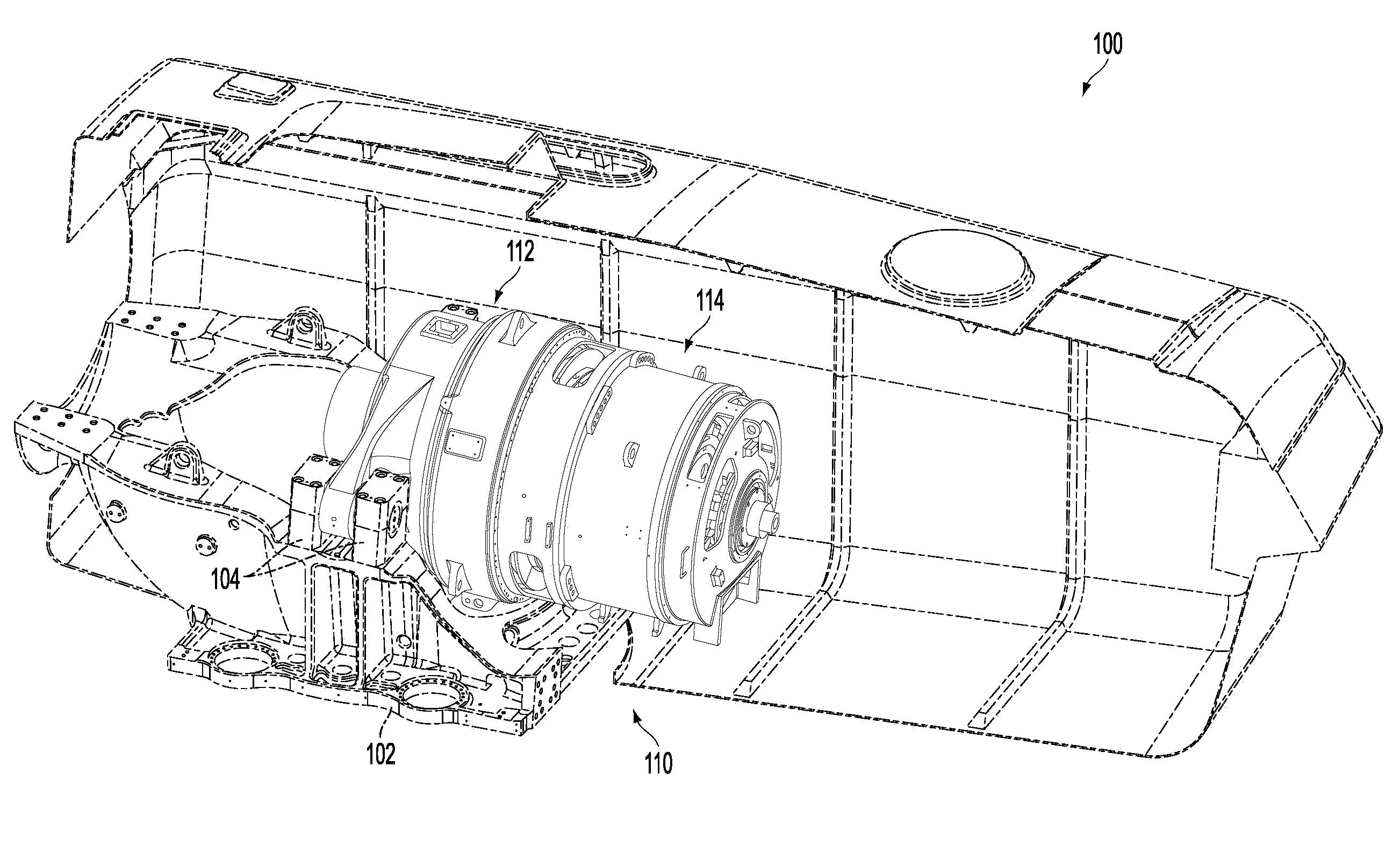
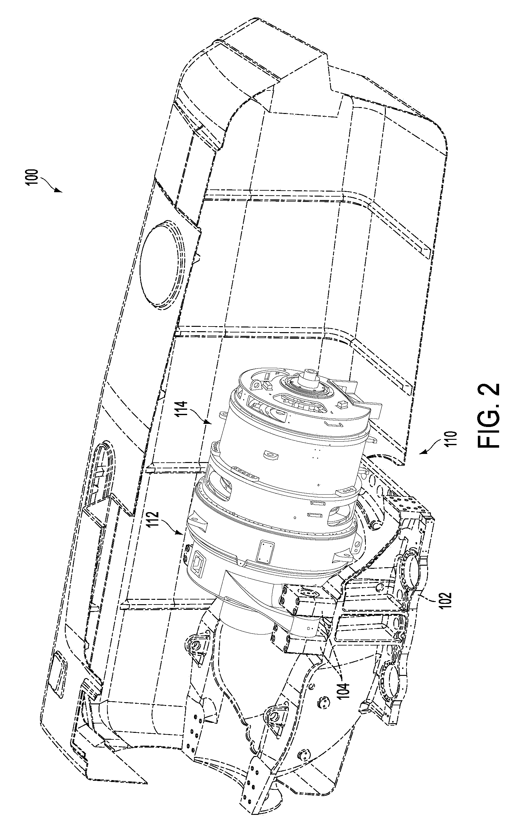
[0005]Various power transmission, and generation systems, and assemblies are provided for a wind turbine. In one embodiment, a power generation system is provided including a transmission having an input axially aligned with an output, the input configured to receive rotary motion generated by a wind driven rotor head, the input located downwind of the output, an electromagnetic apparatus having an input configured to be coupled to the transmission output, and a bearing configured to radially support both the transmission output and the electromagnetic apparatus input. In this way, a common bearing may support both the transmission and electromagnetic apparatus, allowing for a more compact and efficient design while retaining service and repair capabilities.

Problems solved by technology

On the other hand, the overall size of a power generation unit in the wind turbine may lead to increased up-tower mass.
However, the inventors herein have recognized several issues with such integration.
For example, assembling, testing, servicing and / or repairing a fully integrated power generation system may be extremely difficult, leaving the wind turbine inoperable.
Therefore, the lifespan of the wind turbine may be significantly reduced or repair and maintenance costs may be excessive.
Furthermore, due to the growth in the wind turbine industry, the global supply chain has delivery pressures, and thus an integrated generator and gearbox having a common housing, or other similar features, may overly restrict the separate manufacturing and supply of the gearbox and generator that would otherwise alleviate delivery pressures.

Method used


Image

  • System and assembly for power transmission and generation in a wind turbine
  • System and assembly for power transmission and generation in a wind turbine
  • System and assembly for power transmission and generation in a wind turbine

Examples


Embodiment Construction

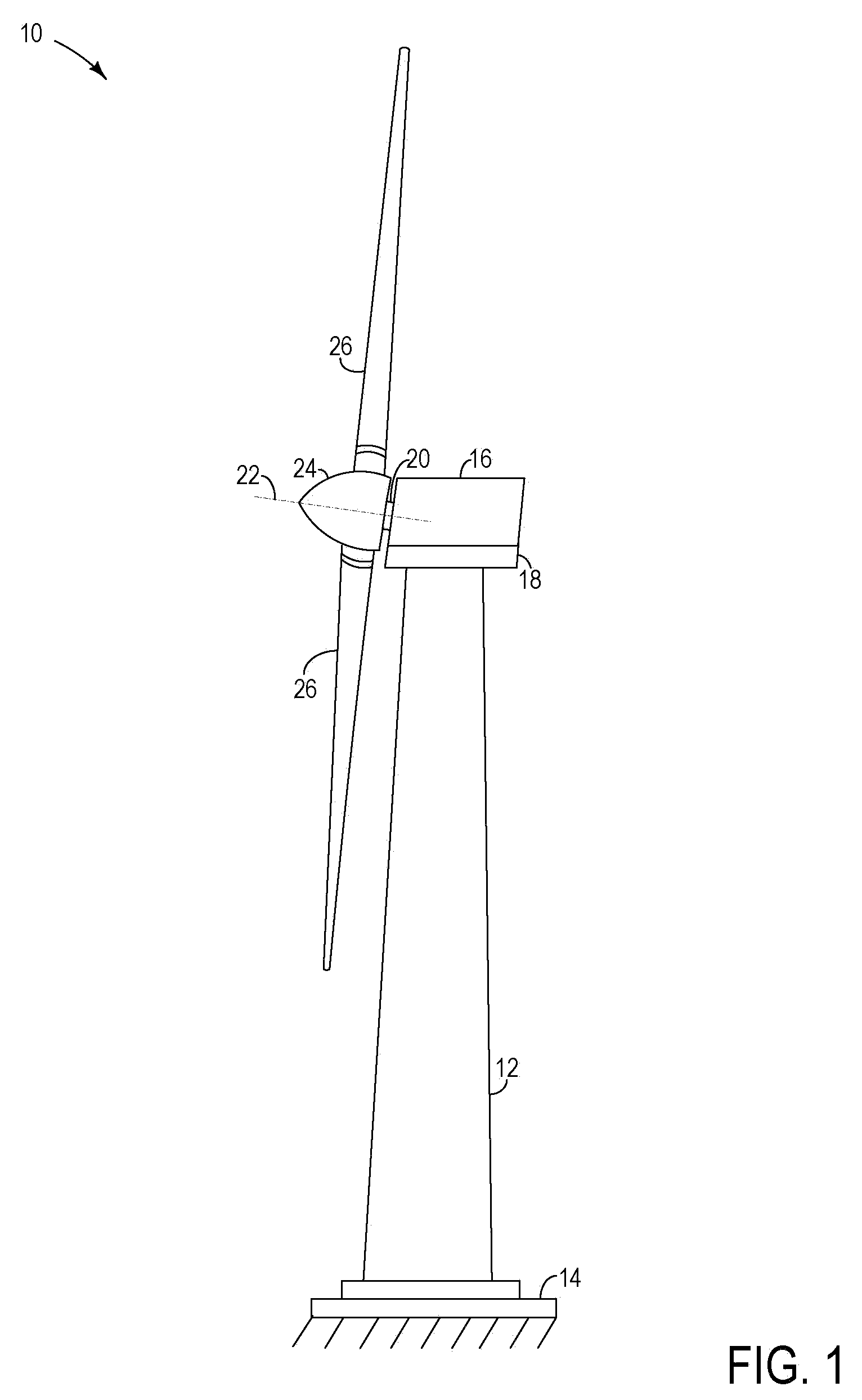
[0018]A power generating wind turbine 10 is shown in FIG. 1. The turbine includes a tower 12 extending substantially vertically out of a base 14. The tower may be constructed from a plurality of stacked components. However, it can be appreciated that alternate configurations of the tower are possible, such as a lattice tower. A nacelle 16 and nacelle bedplate 18 are positioned atop the tower. A drive unit (not shown) may be included in the nacelle bedplate, allowing the nacelle to rotate about a horizontal plane. The nacelle may be positioned, by the drive unit, directly into the wind, increasing the power output of the wind turbine. Further in some examples, a drive unit controls the vertical pitch of the blades. The nacelle houses a power generation system having a transmission and an electromagnetic apparatus, shown in FIG. 2 discussed in greater detail herein. Further, various power electronics and control electronics may be housed in nacelle 16.

[0019]A main shaft 20 extends out...


PUM


Abstract

Various power transmission and generation systems and assemblies are provided for a wind turbine. In one embodiment, a power generation system is provided including a transmission having an input axially aligned with an output, the input configured to receive rotary motion generated by a wind driven rotor head, the input located downwind of the output, an electromagnetic apparatus having an input configured to be coupled to the transmission output, and a bearing configured to radially support both the transmission output and the electromagnetic apparatus input. In this way, a common bearing may support both the transmission and electromagnetic apparatus, allowing for a more compact and efficient design while retaining service and repair capabilities.

Description

FIELD[0001]The present application relates to power systems of wind turbines.BACKGROUND[0002]Due to the high growth rate of the wind turbine industry, an increasing number of power generation components have been developed by a multitude of companies. Many of these companies independently design and manufacture various components included in the power generation system of the wind turbine, such as gearboxes and generators. In this way, manufactures select a desired gearbox, generator, etc., in designing the overall wind turbine. On the other hand, the overall size of a power generation unit in the wind turbine may lead to increased up-tower mass.[0003]As such, various approaches may be used to integrate one or more components of a wind turbine, such as integrating a gearbox and generator in a common housing to form an integrated power generation system.[0004]However, the inventors herein have recognized several issues with such integration. For example, assembling, testing, servicin...

Claims


Application Information

Patent Timeline
IPC IPC(8): F03D11/02F16H47/04
CPCF03D11/0008F03D11/02Y02E10/725F16H1/28Y02E10/722F05B2260/40311F03D80/70F03D15/00F03D9/25F03D15/10Y02E10/72
Inventor CISZAK, ROBERTKUZMA, TIMOTHY
Owner HANSEN TRANSMISSIONS
Features
  • Generate Ideas
  • Intellectual Property
  • Life Sciences
  • Materials
  • Tech Scout
  • Unparalleled Data Quality
  • Higher Quality Content
  • 60% Fewer Hallucinations
Learn More