Ultrasound-guided ablation method and ultrasound-guided ablation system

an ablation system and ultrasound technology, applied in the field of ultrasound-guided ablation and ultrasound-guided ablation systems, can solve the problems of ultrasound image, inability to determine how much margin the ablation actually has been performed,

Inactive Publication Date: 2010-03-11
OLYMPUS MEDICAL SYST CORP
View PDF2 Cites 41 Cited by
  • Summary
  • Abstract
  • Description
  • Claims
  • Application Information

AI Technical Summary

Problems solved by technology

However, in an ultrasound image, the boundary between an ultrasound image of the objective area such as a lesion and an ultrasound image of surrounding tissues become unclear, because the protein of the ablated tissue is denatured.
As a result, even if the ablation is performed with the margin of 5 mm, with how much margin the ablation has been actually performed may not be able to be determined from the ultrasound image after the ablation.

Method used


Image

  • Ultrasound-guided ablation method and ultrasound-guided ablation system
  • Ultrasound-guided ablation method and ultrasound-guided ablation system
  • Ultrasound-guided ablation method and ultrasound-guided ablation system

Examples


first embodiment

[0088]the present invention will be described with reference to FIGS. 1 to 16B.

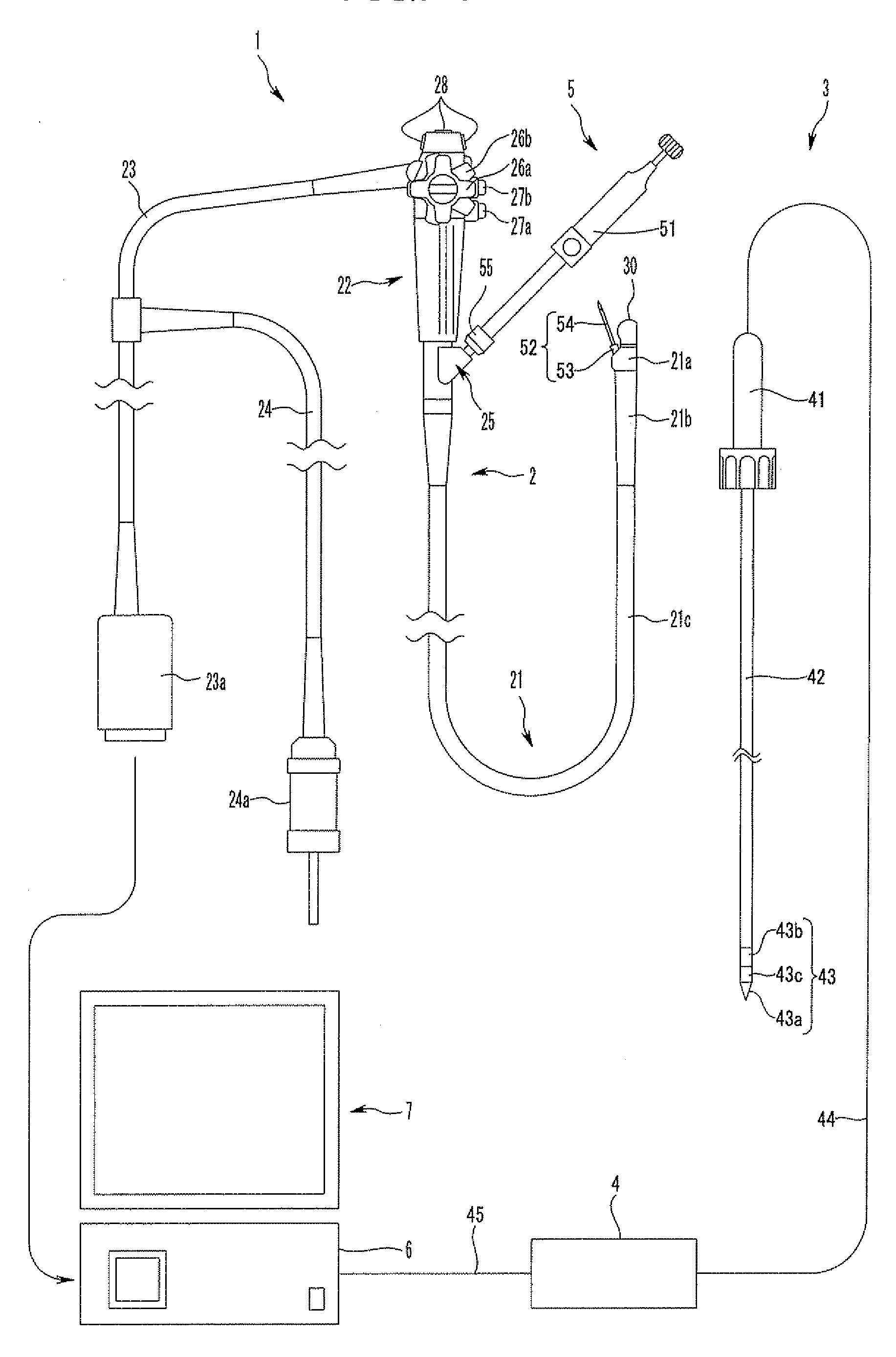
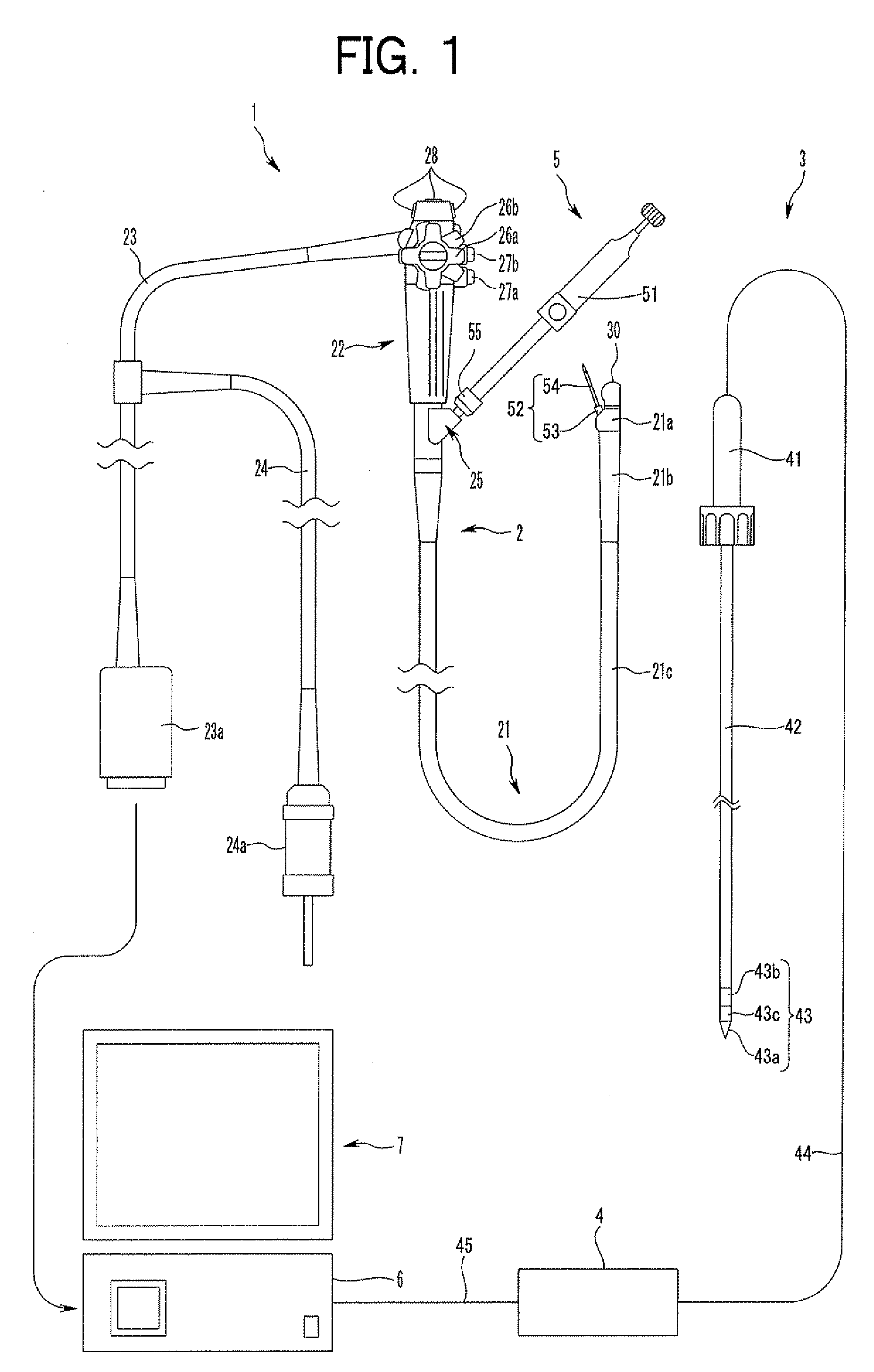
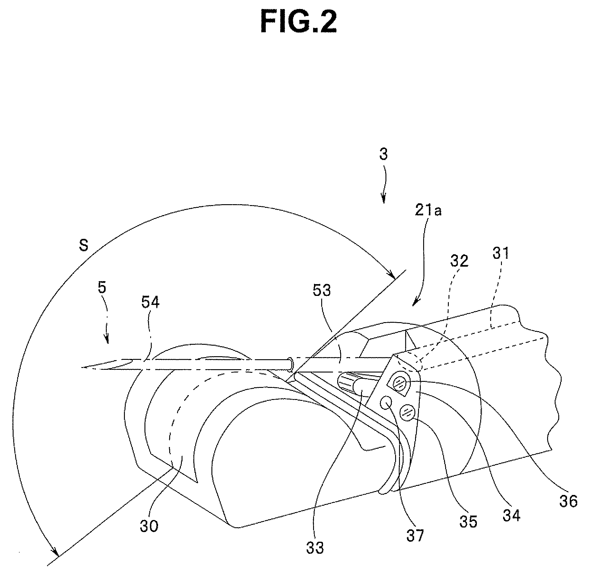
[0089]As shown in FIG. 1, an ultrasound endoscope-guided ablation system 1 of the present embodiment is mainly constituted by an ultrasound endoscope (hereinafter abbreviated as EUS) 2 that is a kind of endoscope, an ablation device 3, an ablation power source device (hereinafter abbreviated as power source device) 4, a puncture needle 5, an ultrasound observation device 6, and a display device 7.

[0090]The EUS 2 is mainly constituted by: an insertion portion 21 inserted into the body; an operation portion 22 located at a proximal end of the insertion portion 21; a universal code 23 extending from a side of the operation portion 22; and a light source cable 24 that is branched, for example, in the middle of the universal code 23.

[0091]An ultrasound connector 23a that can be attached to and detached from the ultrasound observation device 6 is arranged at a proximal end portion of the universal code 23. An e...

second embodiment

[0161]the present invention will be described with reference to FIGS. 17 to 37.

[0162]As shown in FIG. 17, configurations of an EUS 2A and an ultrasound observation device 6A of the first embodiment are different in an ultrasound endoscope-guided ablation system 1A of the present embodiment.

[0163]The ultrasound observation device 6A includes, as an ablation target area specifying unit, a peripheral border input unit 6A1, a computing unit 6A2, an ablation margin setting unit 6A3, and an image processing unit 6A4. Reference numeral 6A5 denotes an input pen.

[0164]The input pen 6A5 is an objective area input function unit and is a device for tracing a line of the peripheral border of the objective area 10 on an ultrasound image 7b displayed on a screen 7a to acquire information of the objective area peripheral line. The peripheral line traced by the input pen 6A5 is displayed on the screen 7a through an image processing unit 6A4 described below. Information of the displayed peripheral li...


PUM


Abstract

An ultrasound-guided ablation method captures an objective area to be ablated in an ultrasound scan area of an ultrasound transducer and delineates the objective area on an ultrasound image; specifies an ablation target area to display the ablation target area with a margin necessary for ablating the objective area on the ultrasound image processed by an ultrasound observation device and displayed on a display device; ablates, by an ablation device, the ablation target area displayed on the ultrasound image; and checks, on the ultrasound image, that an ablated area ablated by the ablation device has reached the ablation target area displayed on the ultrasound image.

Description

BACKGROUND OF THE INVENTION[0001]1. Field of the Invention[0002]The present invention relates to an ultrasound-guided ablation method and an ultrasound-guided ablation system for treating an objective area such as tumor by ablation under the guidance of ultrasound.[0003]2. Description of the Related Art[0004]Conventionally, a treatment procedure has been known in which an ablation apparatus, such as a radio-frequency ablation device, a high-frequency ablation device, and a micro-wave ablation device, is punctured under the guidance of ultrasound from the body surface to liver tumor or the like to ablate an objective area such as a lesion.[0005]In recent years, an ultrasound endoscope-guided ablation procedure is being studied as an example in which an ultrasound endoscope provided with a linear / convex transducer is used for performing the procedure.[0006]In the ablation procedure, leaving a diseased tissue such as a tumor cell needs to be prevented. Therefore, it is desirable to abl...

Claims


Application Information

Patent Timeline
Patent Type & Authority Applications(United States)
IPC IPC(8): A61B8/00
CPCA61B1/00098A61B1/018A61B8/0833A61B8/0841A61B8/12A61B2018/00875A61B8/4488A61B18/1206A61B18/1477A61B2018/00577A61B8/445A61B2018/00982A61B2090/3784
Inventor NISHINA, KENICHINAKAZATO, TAKEHARUKASAHARA, HIDEYUKIYAMADA, NORIHIROSAWADA, YUKIHIKOOTANI, SHUJIECHIZENYA, TAKAHIRO
Owner OLYMPUS MEDICAL SYST CORP
Why Eureka
Try Eureka