Ultrasound endoscope system and ultrasound observation method

Inactive Publication Date: 2010-03-11
OLYMPUS MEDICAL SYST CORP
View PDF5 Cites 76 Cited by
  • Summary
  • Abstract
  • Description
  • Claims
  • Application Information

AI Technical Summary

Problems solved by technology

However, reliable medical treatment may be unable to be performed only by such procedures using a puncture needle.
For example, when a cyst of a p

Method used


Image

  • Ultrasound endoscope system and ultrasound observation method
  • Ultrasound endoscope system and ultrasound observation method
  • Ultrasound endoscope system and ultrasound observation method

Examples


first embodiment

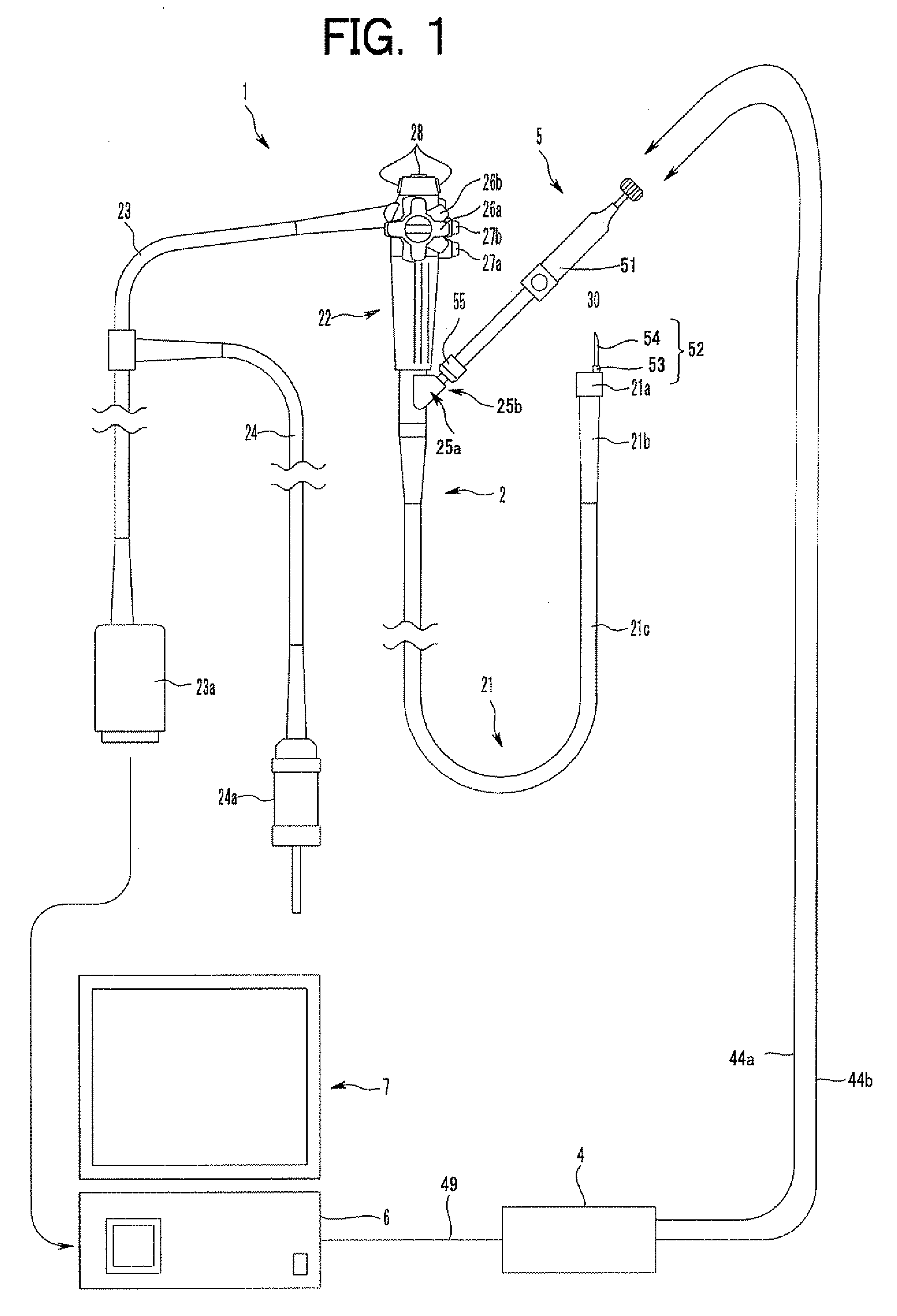
[0041]FIGS. 1 to 21 relate to a first embodiment of the present invention, and FIG. 1 is an explanatory diagram showing an ultrasound endoscope system according to the first embodiment of the present invention. In addition, hereafter, an ultrasound endoscope is abbreviated to an EUS.

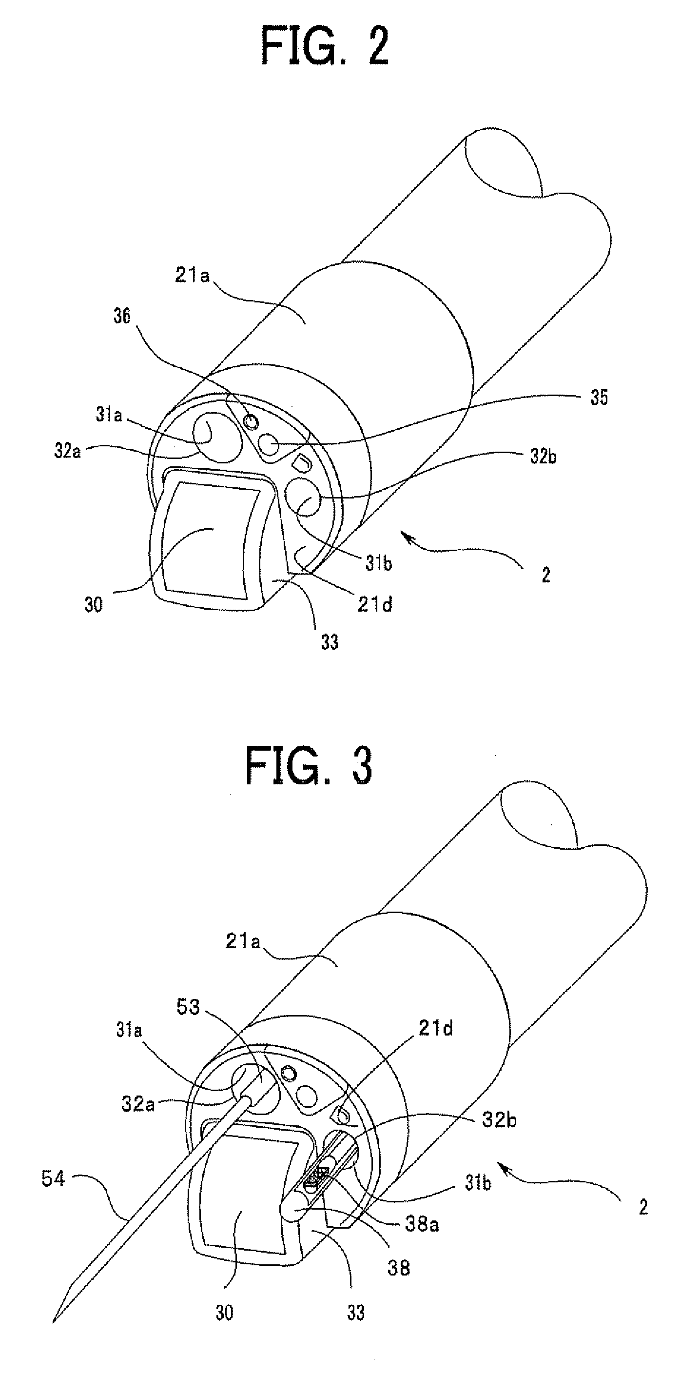
[0042]As shown in FIG. 1, an EUS system 1 of the present embodiment comprises an EUS 2 which is one of endoscopes, a puncture needle 5, an ultrasound observation apparatus 6, and a display unit 7. Furthermore, the EUS system 1 comprises an ultrasound probe 38 (refer to FIG. 3) provided insertably and extractably in a channel of the EUS 2, an ultrasound probe 71 (refer to FIG. 7) provided insertably and extractably in a needle tube of the puncture needle 5, and stylets 90 (refer to FIG. 5) and 90a (refer to FIG. 11) provided insertably and extractably in the needle tube of the puncture needle 5.

[0043]The EUS 2 mainly includes an insertion portion 21 inserted into an interior of a body, an operation portio...

modified example

[0153]FIGS. 22 and 23 are outline perspective views showing a modified example of the EUS.

[0154]An EUS 2A in FIGS. 22 and 23 differs from the EUS 2 in FIGS. 2 and 3 in that not only an ultrasound transducer 30a is used in place of the ultrasound transducer 30, but also a protruding portion 131 is provided.

[0155]The ultrasound transducer 30a of the EUS 2A in FIGS. 22 and 23 has a surface approximately parallel to the distal end surface 21d, and its protruding quantity from the distal end surface 21d is very small. Hence, the protruding portion 33 does not exist in the ultrasound transducer 30a.

[0156]On the other hand, the protruding portion 131 is provided in the EUS 2A similarly to the protruding portion 33. Thereby, the protruding portion 131 is delineated by the ultrasound probe 38. The protruding portion 131 is provided in a position except on a line linearly connecting the distal end openings 32a and 32b mutually. In addition, in order that ultrasound observation of the protrud...

second embodiment

[0181]FIGS. 30 and 31 are explanatory diagrams showing a second embodiment of the present invention.

(Injection Using Ultrasound Contrast Agent)

[0182]The present embodiment facilitates observation in the case of performing injection by the puncture needle 5 after a puncture. For example, there is an EUS-guided celiac plexus block as a pain relaxation therapy of a terminal pancreatic cancer. In order to paralyze or destroy a nerve plexus, ethanol is injected into celiac plexus through a needle which is punctured under EUS guide. Nevertheless, it is hard to see the injected ethanol on an ultrasound image. For this reason, it was difficult to confirm whether the injected ethanol was spread to a desired area.

[0183]In the present embodiment, what contains an ultrasound contrast agent as a medicine to be injected is adopted. As the ultrasound contrast agent, there are Definity (registered trademark) (Bristol-Myers Squibb), Sonazoid (registered trademark), and the like.

[0184]An operator con...


PUM


Abstract

When an ultrasound endoscope arrives at an objective area, a puncture needle is located in a scan area of a first ultrasound image. Thereby, an image of the puncture needle is delineated on the first ultrasound image. Furthermore, an ultrasound probe is inserted into the puncture needle and an ultrasound transducer of the ultrasound probe is arranged in the objective area through the puncture needle. Then, the ultrasound probe is driven and a second ultrasound image is delineated. Detailed observation inside the objective area in which the puncture needle is punctured is possible with the second ultrasound image.

Description

BACKGROUND OF THE INVENTION[0001]1. Field of the Invention[0002]The present invention relates to an ultrasound endoscope system and an ultrasound observation method for observing an objective area under the guidance of the ultrasound endoscope.[0003]2. Description of Related Art[0004]Usually, under the guidance with an ultrasound endoscope, a lesion is punctured with a puncture needle inserted from a treatment instrument channel of the ultrasound endoscope, and a tissue is sucked and sampled from the lesion to diagnose pathologically. In addition, in recent years, by applying this procedure, for example, a drainage procedure which discharges a cyst fluid and the like which are stored in a lesion, such as a cyst of a pancreas, and also an injection procedure which injects a liquid medicine into an objective area, such as a lesion of a cancer, or nerve plexus has been performed.[0005]However, reliable medical treatment may be unable to be performed only by such procedures using a punc...

Claims


Application Information

Patent Timeline
IPC IPC(8): A61B8/14
CPCA61B1/018A61B8/445A61B8/12
Inventor NISHINA, KENICHISATO, MASATOSHINAKAZATO, TAKEHARUSATO, SUNAOIMAHASHI, TAKUYATSUTAKI, SHINICHI
Owner OLYMPUS MEDICAL SYST CORP
Why Eureka
Try Eureka