Bifurcated medical device for treating a target site and associated method

a medical device and target site technology, applied in the field of medical devices, can solve the problems of weak vessel wall, balloon expansion, and bursting, and achieve the effects of reducing the delivery profile, improving delivery ease, and reducing the trauma of the vessel

Inactive Publication Date: 2010-03-11
ST JUDE MEDICAL CARDILOGY DIV INC
View PDF32 Cites 85 Cited by
  • Summary
  • Abstract
  • Description
  • Claims
  • Application Information

AI Technical Summary

Benefits of technology

[0014]According to one embodiment, the first ends of the first and second portions are configured to engage a lumen upstream of an aneurysm such that the opening substantially conforms to a diameter of the lumen. The second ends of the first and second portions may be configured to engage respective branches of the bifurcated lumen downstream of the aneurysm. The first and second portions may also be configured to be coaxially aligned for delivery within a catheter to reduce the delivery profile, to reduce trauma to the vessel, and improve the ease of delivery through smaller vessels and more difficult to reach anatomy.

Problems solved by technology

As blood flows through the aorta, the weak vessel wall thins over time and expands like a balloon and can eventually burst if the vessel wall gets too thin.
Endoleaks may occur as a result of blood flowing around the stent, which may result in further weakening of the site of the aneurysm.
Thus, the delivery of the bifurcated stent graft may be complicated when attempting to position the tubular portions of the bifurcated stent graft into respective iliac arteries while also ensuring that the main portion is secured within the aorta upstream of the aneurysm without blocking the renal arteries.
Furthermore, the size of the delivery catheter may affect the ability of the surgeon to manipulate the catheter within the lumen, often reduced in size due to arteriosclerosis, and may result in trauma to the vascular tissue.

Method used


Image

  • Bifurcated medical device for treating a target site and associated method
  • Bifurcated medical device for treating a target site and associated method
  • Bifurcated medical device for treating a target site and associated method

Examples


Embodiment Construction

[0034]The present invention now will be described more fully hereinafter with reference to the accompanying drawings, in which some, but not all embodiments of the invention are shown. Indeed, this invention may be embodied in many different forms and should not be construed as limited to the embodiments set forth herein; rather, these embodiments are provided so that this disclosure will satisfy applicable legal requirements. Like numbers refer to like elements throughout.

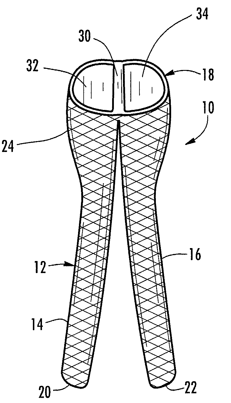
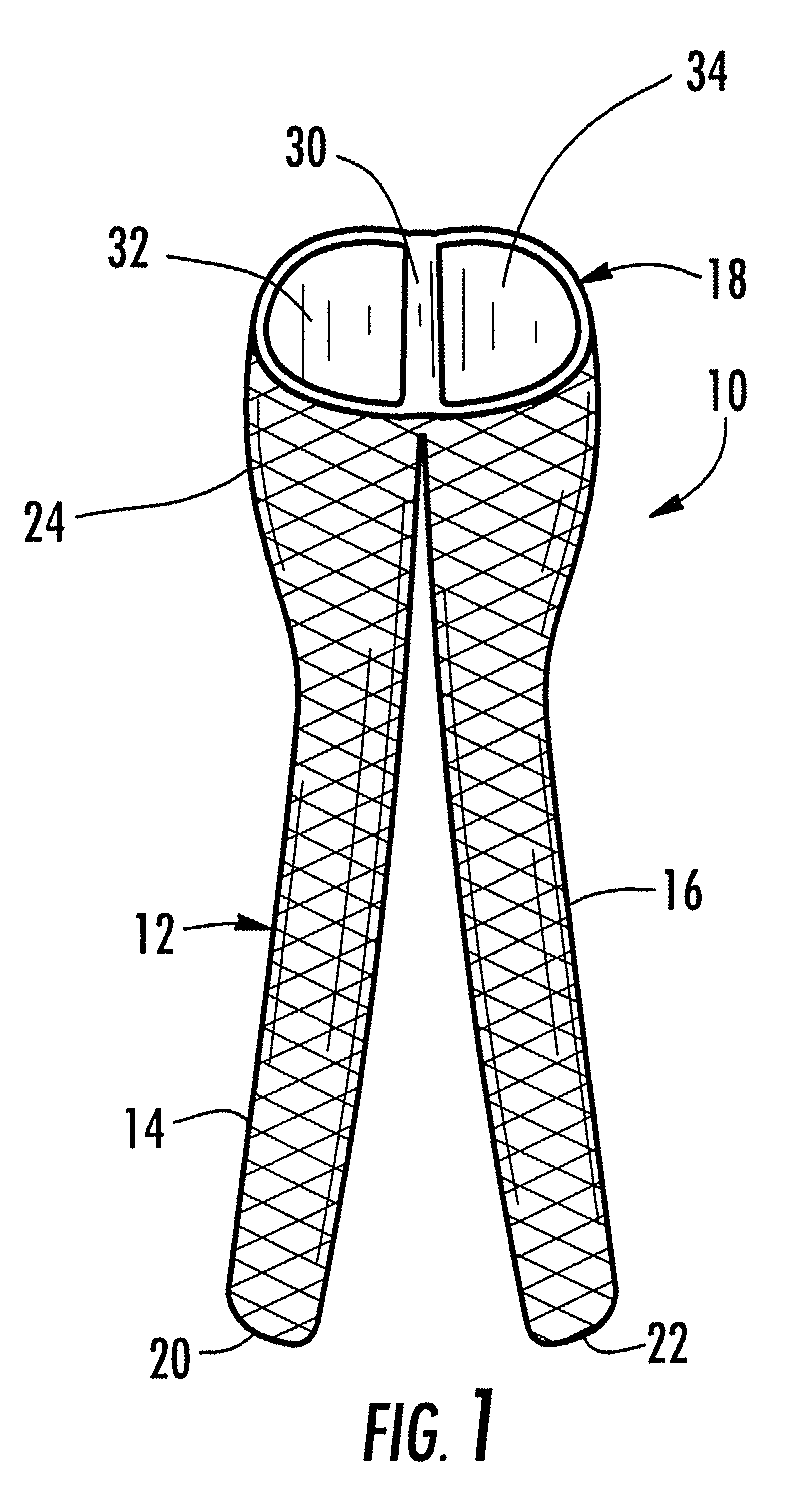
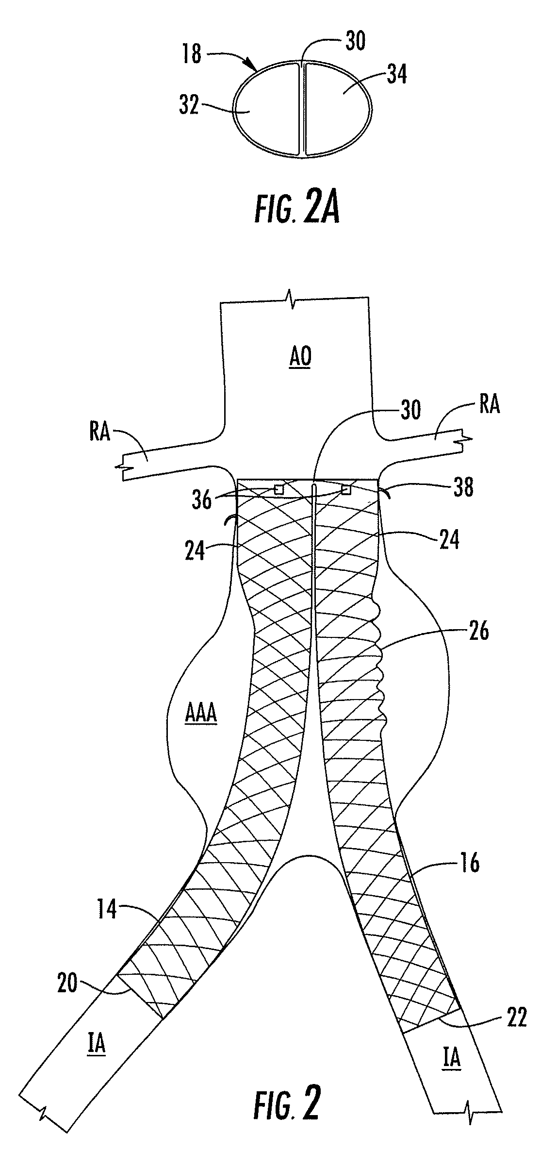
[0035]Embodiments of the present invention provide a medical device for use in treating a target site within the body, such as a stent graft for excluding various vascular abnormalities, which may include, for example, excluding an aneurysm. The device may also be used as a flow restrictor or a shunt, filter or other type of device for placement in the vascular system, as well as a graft for lining a lumen of a vessel. It is understood that the use of the term “target site” is not meant to be limiting, as the devi...


PUM


Abstract

Embodiments of the present invention provide medical devices and methods for treating a target site within the body. For example, one embodiment provides a stent graft for treating a target site proximate to a bifurcated lumen, wherein the stent graft includes a first tubular structure having proximal and distal ends and a side wall extending therebetween. The first tubular structure includes an opening defined within the side wall and is configured to define a first portion having first and second ends and a second portion having first and second ends. The opening corresponds to the first ends of the first and second portions and the second ends of the first and second portions respectively correspond to the proximal and distal ends of the first tubular structure, and at least a portion of the first and second portions are configured to be positioned within respective branches of a bifurcated lumen.

Description

BACKGROUND OF THE INVENTION[0001]1) Field of the Invention[0002]The present invention relates to medical devices and, in particular, to a medical device for treating a target site within the body, such as a vascular abnormality, proximate to a bifurcated lumen.[0003]2) Description of Related Art[0004]An aortic aneurysm is a weak area in the aorta, the main blood vessel that carries blood from the heart to the rest of the body. A common aneurysm is the abdominal aortic aneurysm (“AAA”), which may be caused by arteriosclerosis. As blood flows through the aorta, the weak vessel wall thins over time and expands like a balloon and can eventually burst if the vessel wall gets too thin. Most commonly, aortic aneurysms occur in the portion of the vessel below the renal artery origins. The aneurysm may be located in the vessels supplying the hips and pelvis, including the iliac arteries.[0005]Rather than performing surgery to repair an aneurysm, vascular surgeons may install an endovascular ...

Claims


Application Information

Patent Timeline
Patent Type & Authority Applications(United States)
IPC IPC(8): A61F2/06
CPCA61F2/07A61F2002/067A61F2230/0034A61F2/90A61F2220/0091A61F2250/0039A61F2/848A61F2210/0076A61F2240/001A61F2250/0067A61F2250/0098B21F45/008A61F2/852
Inventor REN, BROOKEADAMS, DANIEL O.OSLUND, JOHN C.
Owner ST JUDE MEDICAL CARDILOGY DIV INC
Why Eureka
Try Eureka