Ship hull structure and a method of operating the ship

a technology of hull structure and hull structure, applied in the field of ships, can solve the problems of indecent looking at and danger, and achieve the effects of reducing the viscosity force in water, increasing propulsion, and rapid gliding speed

Active Publication Date: 2010-03-18
HUANG BILL WEN CHANG
View PDF7 Cites 21 Cited by
  • Summary
  • Abstract
  • Description
  • Claims
  • Application Information

AI Technical Summary

Benefits of technology

[0014]A fifth object of the present invention is to provide a method of operating an articulated, wherein when a ship which docks at a port or a pier sets to sail, the rearbody is lifted up by an ascending device to let part or entirety of the propellers be away from a water surface, so as to reduce a viscosity force in water. After the engines have been accelerated to a high rotation speed (RPM) in a short time, the propellers are put into water by the ascending device again, to increase propulsion, enabling the ship to quickly achieve a gliding speed. Next, during sailing, when facing pitching from waves, the rearbody will automatically sway upward and downward in accordance with the ascending and descending (swaying) of the main hull, with a hinge shaft as a pivot, by a buoyancy force of water and weight of the rearbody as well as the reaction force of water against the running propeller, so as to keep at a normal draught condition, thereby maintaining a best sailing state and being able to save fuel.

Problems solved by technology

However, these patents never disclose nor imply that when this kind of articulated ship sets sail or navigates, the rearbody can be lifted up or put down by a hoisting method to adjust a pitching angle with respect to the forebody, thereby adjusting a propeller at a desired waterline height or setting the propeller to sway in the adjusted pitching angle.
Moreover, for the aforementioned conventional articulated ship structure, the hinge coupling device of the fore and aft hull sections is directly exposed outside, which is indecent to be looked at and is dangerous.

Method used


Image

  • Ship hull structure and a method of operating the ship
  • Ship hull structure and a method of operating the ship
  • Ship hull structure and a method of operating the ship

Examples


Embodiment Construction

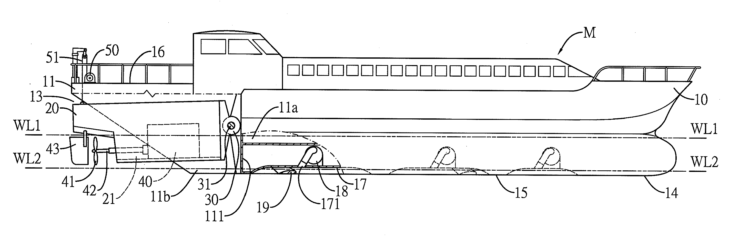
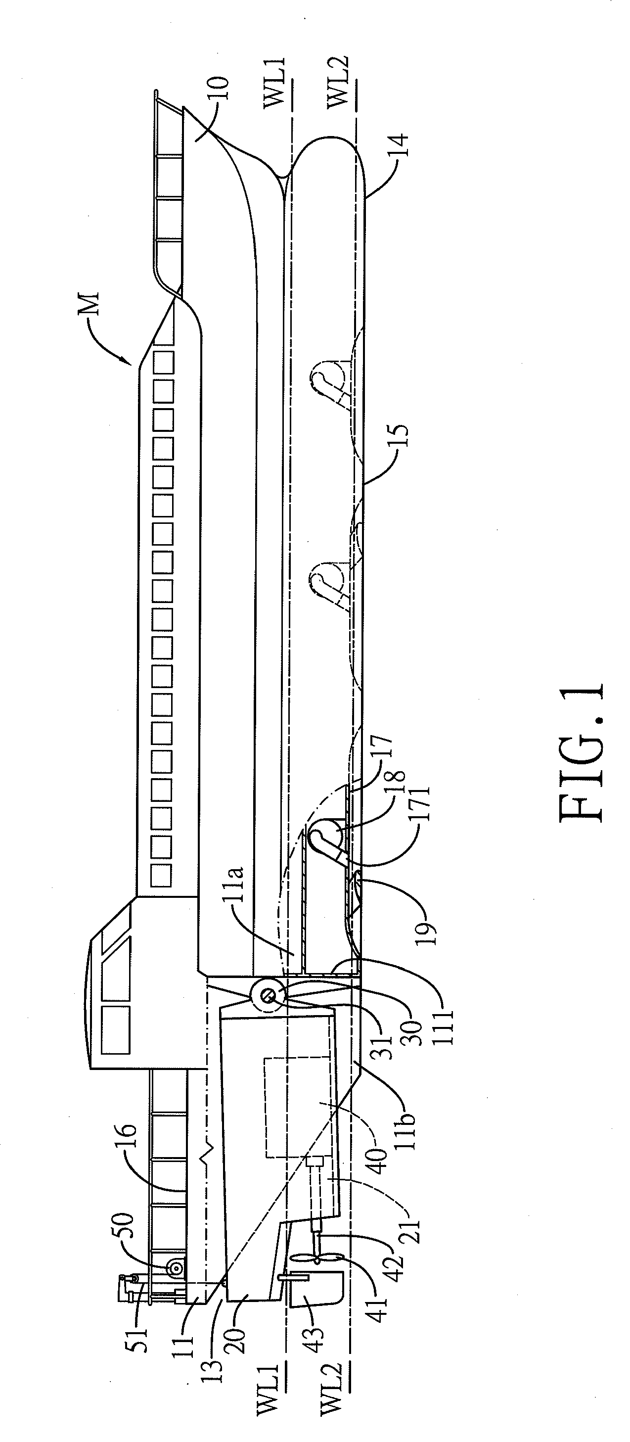
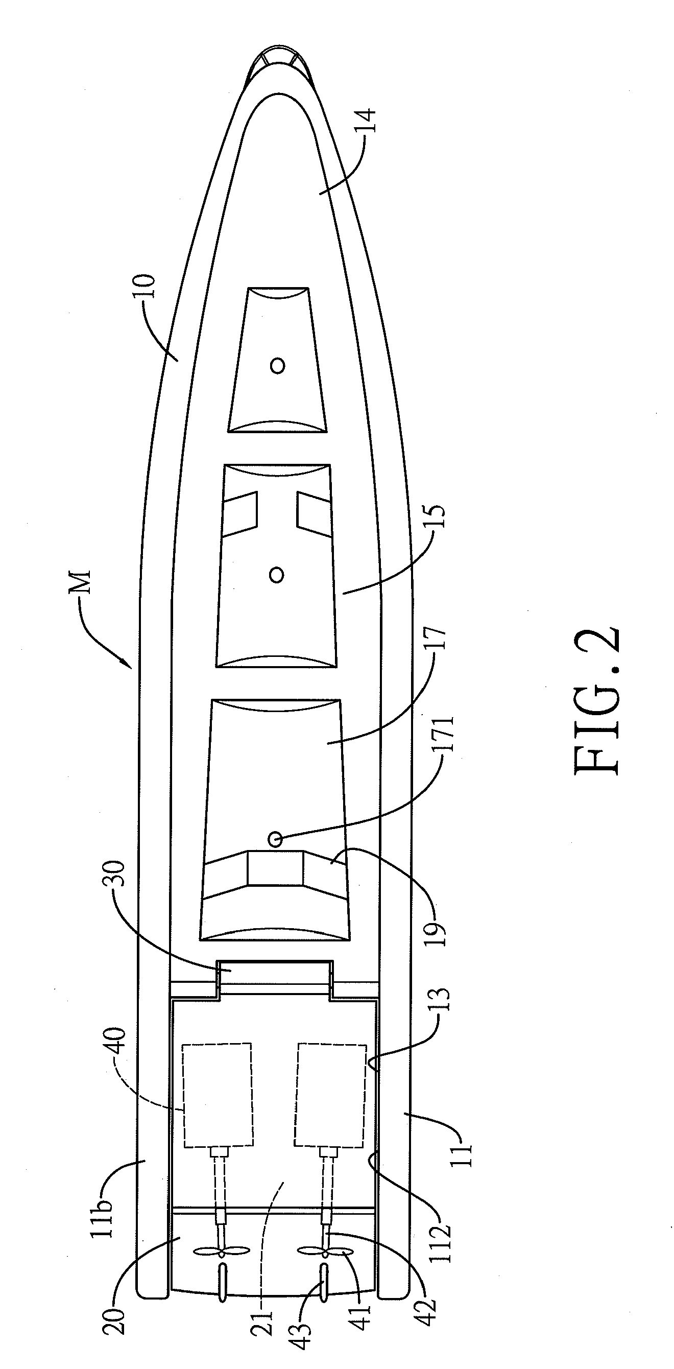
[0022]FIG. 1 shows a side view of implementation configuration that a ship hull structure of the present invention is applied to a yacht, FIG. 2 shows a bottom view of the ship in FIG. 1, and FIG. 3 shows a schematic view of a stern of the ship in FIG. 1

[0023]Referring to FIGS. 1 to 3, a ship M of the present invention comprises a main hull 10 and a rearbody 20 which is connected at a stern portion 11 of the main hull 10 by a hinge coupling device (or briefly called a hinge device) 30 that the rearbody 20 can move upward and downward with respect to the main hull 10.

[0024]An interior of the main hull 10 is provided with cabins and refrigerators (not shown in the drawings) which are required in an ordinary ship. The stern portion 11 is formed with a cavity portion 13 which is extended from a stern end toward a bow. A close-end wall of this cavity portion 13 is a rear wall 111 of a stern cabin 11a, and two side walls are two opposite side walls 112 of two side cabins 11b, extended fro...


PUM


Abstract

A ship hull structure includes a main hull and a movable rearbody having an engine and a propeller. The movable rearbody is located at a lower side of a stern of the main hull, connected with an aft of the main hull to form an integral unit by a hinge linking device allowing the rearbody to pivot up and down. By a block, a crane or a winch and through a chain or a hanging wire, a pivoting angle of the movable rearbody with respect to the main hull can be adjusted and controlled. A bottom of the hull can be provided with at least one, usually plural, air cushion recess, which is filled with pressurized air to reduce a viscous force between a bottom of the ship and water. When a ship of this kind of structure is sailing, the rearbody can be lifted up by the block or the winch, allowing part of the propeller to be separated from a water surface to reduce resistance in the water that the engine can achieve a required rotational speed (RPM) in a short time. Next, the rearbody is laid down slowly, allowing the propeller to be put into the water, thereby increasing propulsion and quickly achieving a cruising speed. When the ship is sailing and encounters with wind wave, the stern will ascend by longitudinal pitching; at this time, the rearbody can descend by its own weight, with a hinge axis as a center, preventing the propeller to leave the water surface to rotate idly. On the other hand, when a bow ascends (that is, the stern descends), the rearbody will maintain a normal draught height by buoyancy of the water and the force between the water and running propeller Therefore, for the entire ship, a wetted surface area of the propeller can be adjusted automatically to keep at a best sailing condition, which can further save fuel consumption significantly. In another embodiment that the bottom of the ship is formed with the air cushion recesses, a friction force of the water can be reduced to increase a ship speed by the air cushion effect formed at the bottom of the ship.

Description

BACKGROUND OF THE INVENTION[0001]a) Field of the Invention[0002]The present invention relates to a ship, and more particularly to a ship hull which is provided with a main hull and a movable rearbody having an engine and a propeller, with the movable rearbody being pivoted at a stern of the main hull by a hinge coupling device that the rearbody is able to move upward and downward with respect to the main hull.[0003]b) Description of the Prior Art[0004]A ship hull is divided into a fore and aft hull sections, and confronting ends of the fore and aft hull sections are connected as an integral unit by a hinge coupling device to constitute an articulated ship, such as the U.S. Pat. Nos. 3,145,681 (issued to ETSUO NAKAGAWA), 3,370,564 (issued to G. ARCHER, et al.), 4,050,395 (issued to ANDERSON) and 6,431,099 (issued to HUANG, the present inventor). All the design objects of these articulated ship structures are to increase a capability of the hulls to overcome hogging and sagging result...

Claims


Application Information

Patent Timeline
Patent Type & Authority Applications(United States)
IPC IPC(8): B63B3/04B63B1/38
CPCB63B1/38B63B3/04Y02T70/122B63H5/125B63B35/70Y02T70/10
Inventor HUANG, BILL WEN-CHANG
Owner HUANG BILL WEN CHANG
Why Eureka
Try Eureka