Fuel cell system

a fuel cell and system technology, applied in the direction of valve operating means/releasing devices, electrical generators, mechanical devices, etc., can solve the problems of not providing specific technology for controlling air pressure, power consumption that cannot be ignored, etc., to improve the response and reliability of fluid control valve driving, and reduce the power consumption required for opening and closing the valve.

Active Publication Date: 2010-03-18
TOYOTA JIDOSHA KK
View PDF2 Cites 8 Cited by
  • Summary
  • Abstract
  • Description
  • Claims
  • Application Information

AI Technical Summary

Benefits of technology

[0018]The present invention provides technology for controlling the pressure of a fluid used for driving a valve. For example, in a preferred aspect of the present invention, the power consumption re...

Problems solved by technology

However, if electromagnetic valves are used for these opening and closing valves, then in the case of a normally open electromagnetic valve, a controlling voltage must be applied continuously to the electromagnetic valve when electric power generation by the fuel cell is stopped in order to keep the electromagnetic valve closed, whereas in the case of a normally closed electromagnetic ...

Method used


Image

  • Fuel cell system
  • Fuel cell system
  • Fuel cell system

Examples


Embodiment Construction

[0028]Preferred embodiments of the present invention are described below based on the drawings.

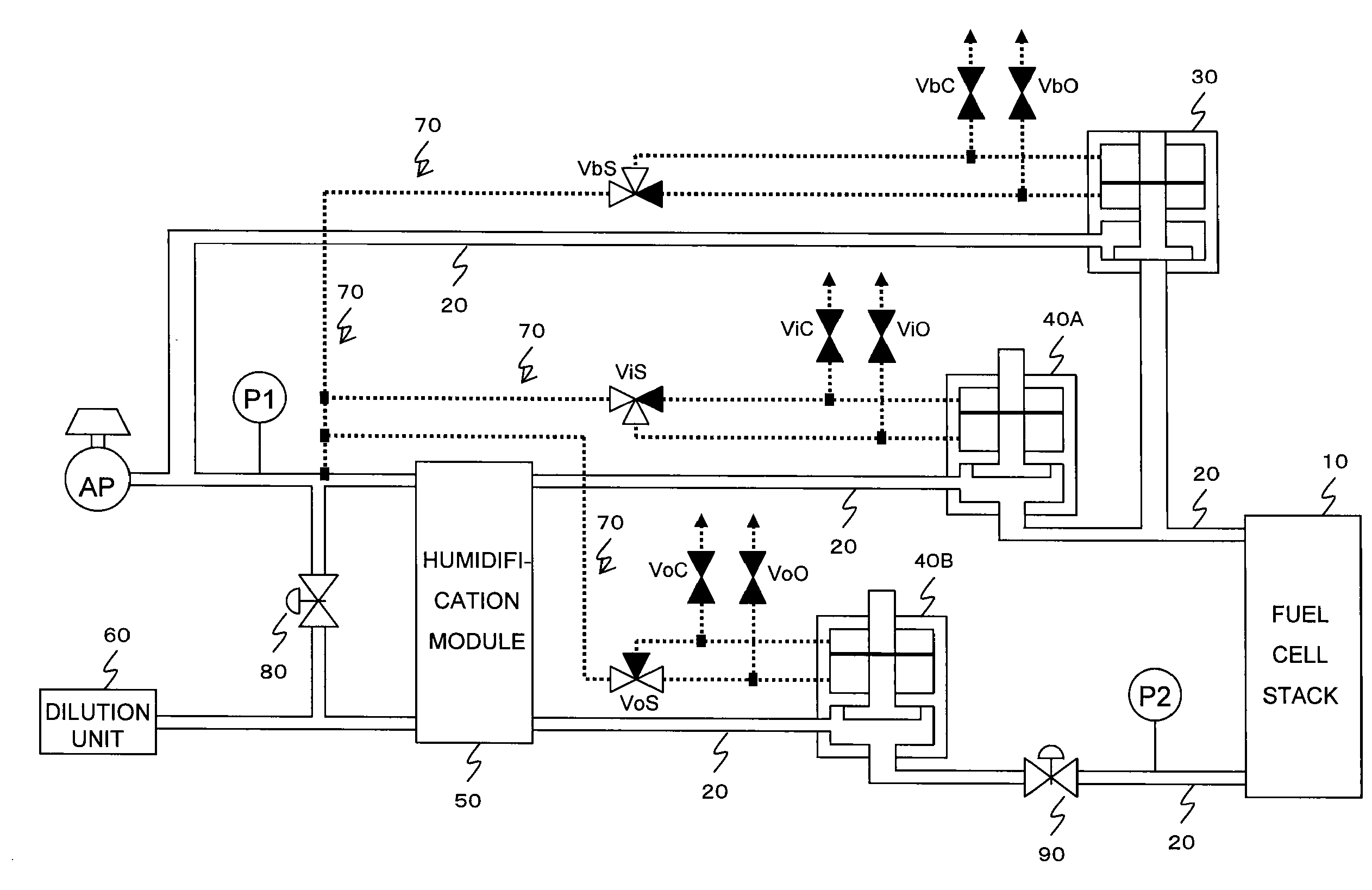
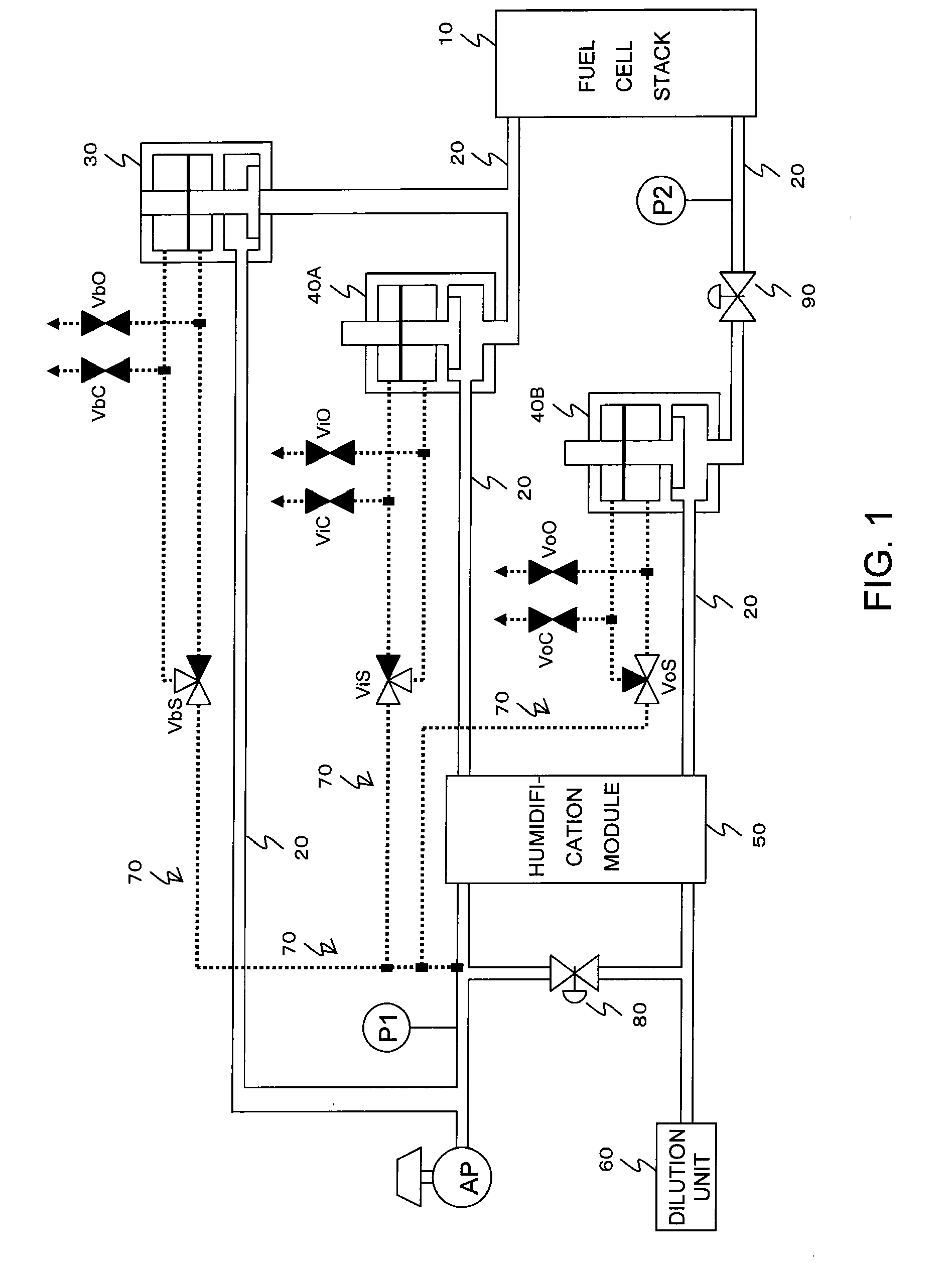
[0029]FIG. 1 is an overall structural diagram illustrating a preferred embodiment of a fuel cell system according to the present invention. The fuel cell system of FIG. 1 comprises a fuel cell stack 10 and a fluid flow path 20 and the like, and a humidification module bypass valve (humidification M bypass valve) 30, an inlet shutoff valve 40A and an outlet shutoff valve 40B that function as fluid control valves are provided within the fluid flow path 20. Moreover, a fuel cell bypass valve 80 and an air pressure regulation valve 90 that function as pressure regulation valves are also provided within the fluid flow path 20.

[0030]The fuel cell stack 10 generates electricity by reacting a fuel gas comprising hydrogen or the like with an oxidizing gas comprising oxygen or the like. In other words, the fuel gas and the oxidizing gas are supplied to the fuel cell stack 10, and electrical energy i...


PUM


Abstract

Fluid control valves, such as a humidifying module bypass valve, an inlet shutoff valve, an outlet shutoff valve are opened and closed by the pressure of air flowing in a fluid flow path. The pressure of air flowing in the fluid flow path is regulated, based on a drive demand pressure emitted to drive the flow control valves, by the flow rate of air discharged from an air compressor, the degree of opening of a fuel cell bypass valve, the degree of opening of an air pressure regulation valve, etc. The drive demand pressure for driving a shutoff valve is set such that, for example, the greater the absolute value of the negative pressure inside the fuel cell stack, the higher the drive demand pressure, and the air pressure is controlled to be the drive demand pressure. Since the pressure of air flowing in the fluid flow path is regulated based on a drive demand pressure of the fluid control valves, the response of drive and reliability of the fluid control valves are better than those in the case where, for example, the pressure is regulated based on a request from a fuel cell.

Description

TECHNICAL FIELD[0001]The present invention relates to a fuel cell system, and more particularly to a technique for driving the opening and closing of valves using the pressure of a fluid flowing through a fluid flow path.BACKGROUND ART[0002]Fuel cell systems that use a fuel gas such as hydrogen and an oxidizing gas such as air to generate electricity are well known. These fuel cell systems are used, for example, by mounting in a vehicle or the like as the power source for a motor used for driving the vehicle. Of course, fuel cell systems can also be used for applications other than vehicles.[0003]A fuel cell system comprises a fuel cell that generates electricity by reacting a fuel gas with an oxidizing gas, and a fluid flow path that supplies the reactant gases, namely the fuel gas and the oxidizing gas, to the fuel cell, and discharges the reacted gases and generated water and the like from the fuel cell.[0004]In this type of fuel cell system, a multitude of technologies have been...

Claims


Application Information

Patent Timeline
IPC IPC(8): H01M8/04
CPCH01M8/04089H01M8/04111Y02E60/50H01M8/0438H01M8/04746H01M8/04126H01M8/04F16K31/12
Inventor OSADA, YASUHIROBONO, TETSUYA
Owner TOYOTA JIDOSHA KK
Why Eureka
Try Eureka