
Separator for non-aqueous secondary battery, process for producing same, and non-aqueous secondary battery

Active Publication Date: 2010-03-18
TEIJIN LTD
View PDF8 Cites 65 Cited by
  • Summary
  • Abstract
  • Description
  • Claims
  • Application Information

AI Technical Summary

Benefits of technology

[0057]A separator of the present invention improves safety of non-aqueous secondary batteries. The separator therefore finds optimum use in a high-energy-density, high-capacity, or high-output-density non-aqueous secondary battery.

Problems solved by technology

The meltdown creates a short circuit inside the battery, and generates a large amount of heat, exposing the battery to the risk of fuming, fire, and explosion.
A drawback of the separators of the type provided with the heat-resistant porous layer, then, is the thickness that exceeds the thickness of about 20 μm commonly adopted by the separators currently available in the market (those solely made from polyethylene or other microporous membranes).
However, the publication does not disclose anything about the shutdown function.
Usually, a sufficient shutdown function cannot be obtained when the thickness of the polyethylene microporous membrane is as small as 4 μm as in this example.
However, when the thickness of the heat-resistant porous layer is reduced too much, the heat resistance will be insufficient, and heat shrinkage occurs over the entire separator in a temperature range including and above the melting point of polyethylene.
This technique appears to successfully reduce the thickness of the heat-resistant porous layer without failing to provide a sufficient heat resistance.
However, Patent Document 4 does not address the heat shrinkage issue of the separator, and as such a battery using the separator of Patent Document 4 has a possibility of heat shrinkage under high temperature.
As described above, concerning the separator including the polyethylene microporous membrane and the heat-resistant porous layer, no technique is available that can sufficiently cope with both the shutdown function and heat resistance issues, and, at the same time, provide a way to reduce the thickness of the separator.
The adhesion between the core and the separator causes a problem when drawing out the core from the electronic element, as it may damage the electronic element being produced.
Another challenge, then, is to improve the slidability of the separator provided with the heat-resistant porous layer.
This issue becomes even more problematic in separators including the heat-resistant porous layer on the both surfaces of the polyethylene microporous membrane, because, in such separators, the heat-resistant porous layer will always be in contact with the core.
The problem remains also in separators including the heat-resistant porous layer only on one surface of the polyethylene microporous membrane, because it undesirably imposes limitations on the orientation of the element, requiring the core to contact the side not provided with the heat-resistant porous layer.
However, the configuration forming the spacer layer is not desirable because it involves large numbers of steps and is complex.

Method used


Image

  • Separator for non-aqueous secondary battery, process for producing same, and non-aqueous secondary battery
  • Separator for non-aqueous secondary battery, process for producing same, and non-aqueous secondary battery
  • Separator for non-aqueous secondary battery, process for producing same, and non-aqueous secondary battery

Examples


example 1-1

[0158]A polyethylene microporous membrane was used that had a unit weight of 6.99 g / m2, a thickness of 11 μm, a Gurley number of 322 seconds (29.3 sec / 100 cc·μm), and a penetration strength of 443 g. The polyethylene microporous membrane had a weight average molecular weight of 1,270,000.

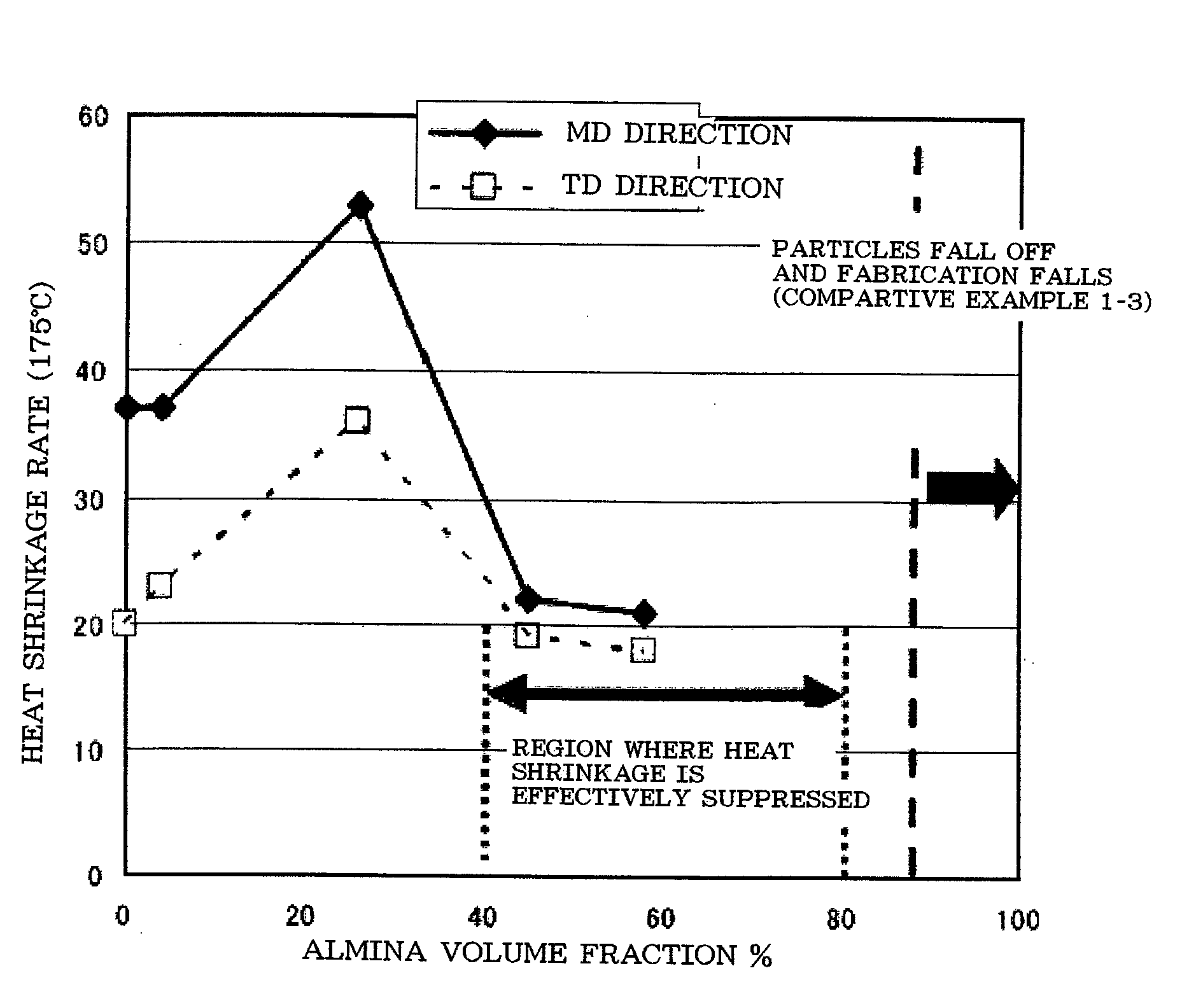
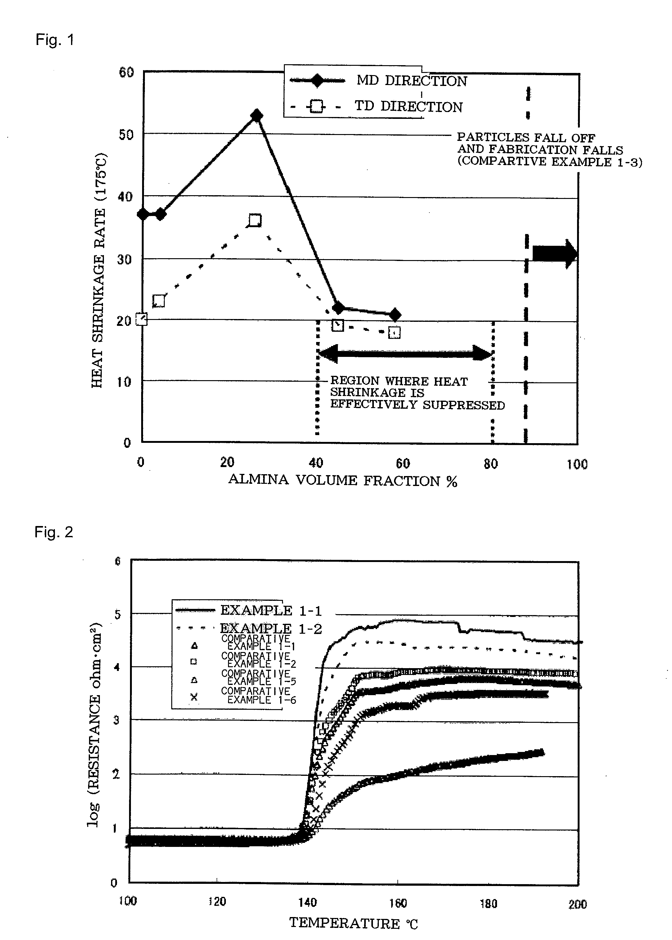
[0159]As the meta-type wholly aromatic polyamide, the poly-m-phenyleneisophthalamide Conex® (Teijin Techno Products Limited) was used. As the inorganic fine particles, α-alumina having an average particle diameter of 0.8 μm (Iwatani Kagaku Kogyo, SA-1) was used. The Conex and the alumina were adjusted to a weight ratio of 30:70 (volume ratio of 55:45), and the mixture was added to a 60:40 weight-ratio mixed solvent of dimethylacetoamide (DMAc) and tripropyleneglycol (TPG) so as to make the Conex content 6 weight %. The resultant mixture was obtained as the coating liquid.

[0160]Two Meyer bars were disposed opposite to each other, and an appropriate amount of the coating liquid was placed therebetween...

example 1-2

[0169]The same polyethylene microporous membrane, meta-type wholly aromatic polyamide, and inorganic fine particles of Example 1-1 were used.

[0170]The Conex and the alumina were adjusted to a weight ratio of 20:80 (volume ratio of 42:58), and the mixture was added to a 60:40 weight-ratio mixed solvent of dimethylacetoamide (DMAc) and tripropyleneglycol (TPG) so as to make the Conex content 6 weight %. The resultant mixture was obtained as the coating liquid.

[0171]Two Meyer bars were disposed opposite to each other, and an appropriate amount of the coating liquid was placed therebetween. The polyethylene microporous membrane was passed between the Meyer bars holding the coating liquid, so as to apply the coating liquid on the both surfaces of the polyethylene microporous membrane. Here, the clearance between the Meyer bars was adjusted to 30 μm, and the both Meyer bars were of size 6. The polyethylene microporous membrane was immersed in a solidifying liquid at 40° C. (water:mixed so...

example 1-3

[0180]The same polyethylene microporous membrane and meta-type wholly aromatic polyamide of Example 1-1 were used.

[0181]As the inorganic fine particles, α-alumina having an average particle diameter of 0.8 μm (Showa Denko, AL160 SG-3) was used. The Conex and the alumina were adjusted to a weight ratio of 15:85 (volume ratio of 34:66), and the mixture was added to a 50:50 weight-ratio mixed solvent of dimethylacetoamide (DMAc) and tripropyleneglycol (TPG) so as to make the Conex content 5.5 weight %. The resultant mixture was obtained as the coating liquid.

[0182]Two Meyer bars were disposed opposite to each other. The clearance between the Meyer bars was adjusted to 30 μm, and the both Meyer bars were of size 6. The polyethylene microporous membrane was passed between the Meyer bars by drawing it while supplying the coating liquid from the both sides of the Meyer bars, so as to apply the coating liquid on the both surfaces of the polyethylene microporous membrane. Then, the polyethyl...


PUM

PropertyMeasurementUnit
Temperatureaaaaaaaaaa
Lengthaaaaaaaaaa
Lengthaaaaaaaaaa

Abstract

A first object of the present invention is to provide a separator including a polyethylene microporous membrane and a heat-resistant porous layer, and that has a sufficient shutdown function and a sufficient heat resistance, and can be formed with a reduced thickness and can overcome the problem of slidability. A first aspect of the present invention is a separator for a non-aqueous secondary battery. The separator includes a microporous membrane of primarily polyethylene, and a heat-resistant porous layer of a primarily heat-resistant polymer formed on at least one surface of the microporous membrane. (1) The microporous membrane has a Gurley number of 25 to 35 sec / 100 cc·μm per unit thickness. (2) The heat-resistant porous layer contains inorganic fine particles having an average particle diameter of 0.1 to 1.0 μm. (3) The inorganic fine particles are 40% to 80% in volume with respect to a total volume of the heat-resistant polymer and the inorganic fine particles. (4) The heat-resistant porous layer has a total thickness of 3 to 12 μm.

Description

TECHNICAL FIELD[0001]The present invention relates to a separator for a non-aqueous secondary battery, and specifically to a separator intended to improve safety of non-aqueous secondary batteries.BACKGROUND ART[0002]A non-aqueous secondary battery as represented by a lithium-ion secondary battery has been pervasive as the main power supply of portable electronic devices, for example, such as cellular phones and laptop computers. The lithium-ion secondary battery has been the subject of ongoing development to obtain higher energy density, higher capacity, and higher output. This trend is expected to increase in the future. To meet such demands, it is of great importance to provide a technique that ensures high battery safety.[0003]The separator for lithium-ion secondary batteries generally uses a microporous membrane made from polyethylene or polypropylene. The separator has a function known as a shutdown function, intended to provide safety for the lithium-ion secondary battery. Th...

Claims


Application Information

Patent Timeline
IPC IPC(8): H01M2/14H01M50/403H01M50/414H01M50/431H01M50/449H01M50/457H01M50/489H01M50/491
CPCH01M2/145H01M2/1653H01M2/1686H01M2/1646H01M10/0525H01M10/4235H01M2/166H01M10/052Y02E60/10H01M50/403H01M50/449Y02P70/50H01M50/457H01M50/491H01M50/414H01M50/431H01M50/489C08J9/22H01M10/05H01M50/463H01M50/417H01M50/423H01M50/446H01M50/443
Inventor NISHIKAWA, SATOSHI
Owner TEIJIN LTD
Learn More