

Resource allocation
- Summary
- Abstract
- Description
- Claims
- Application Information
AI Technical Summary
Benefits of technology
Problems solved by technology
Method used
Image

Examples
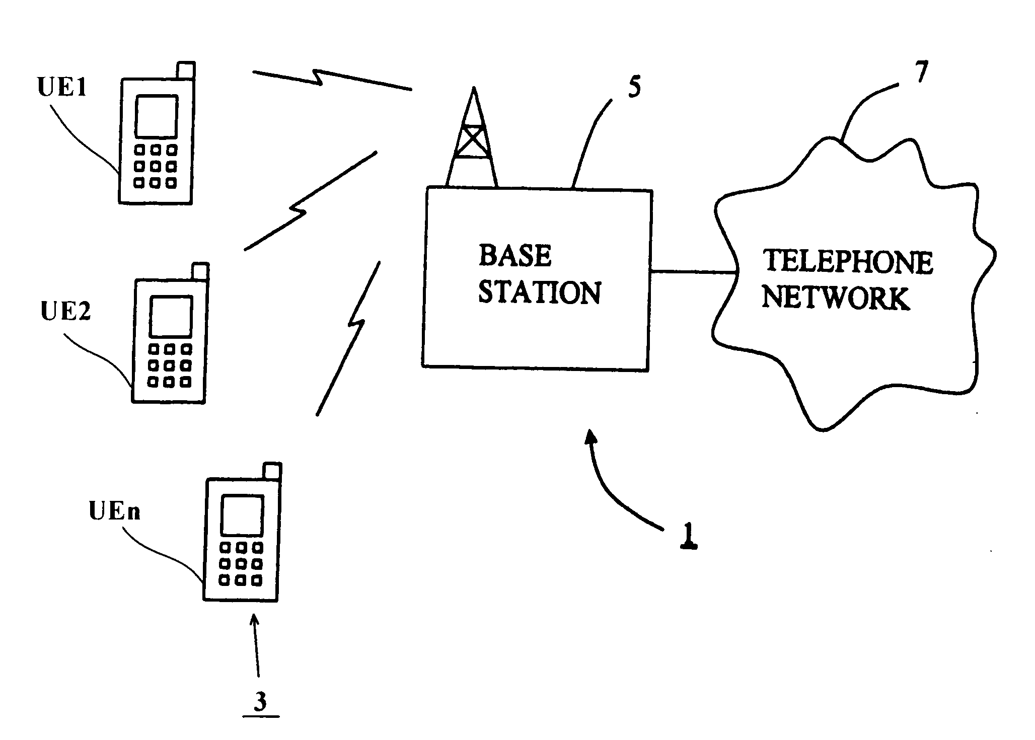
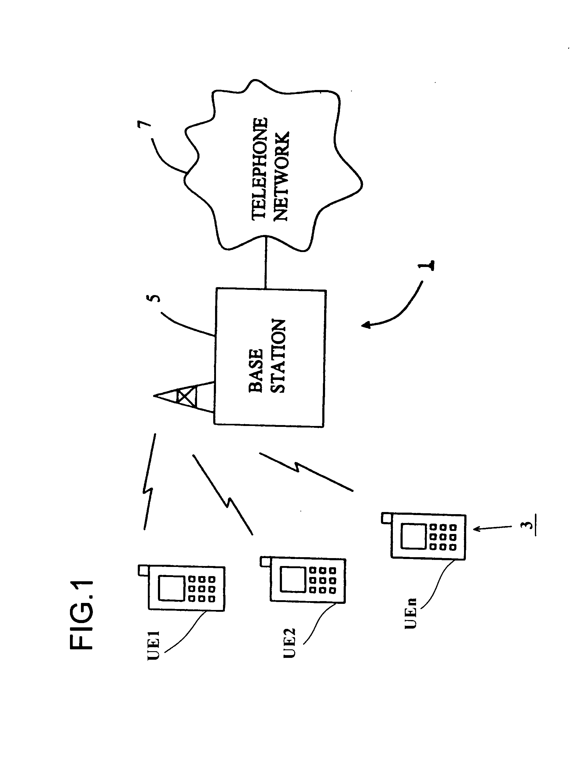
first example
[0112]A first method in accordance with the invention for signalling downlink resource allocation will now be explained with the aid of FIG. 4 which shows a diagram representing part of a TTI 50 of frequency division multiplexed resource blocks RB and comprising a fixed size shared control channel set 51 monitored by the mobile telephones and a shared data channel 52.
[0113]FIG. 4 shows downlink resource allocation for mobile telephones UE1 to UEn. This figure shows the case for individually coded control channels and illustrates an example where a mobile telephone UE1 is scheduled to receive data on three discontinuous localised resource block allocations RB1, RB3 and RB5. We are not proposing here any multiplexing scheme for the downlink L1 / L2 control channels.
[0114]As shown, the resource allocation module 33 has in this example allocated resource blocks RB1, RB3 and RB5 of the shared data channel to mobile telephone UE1, resource block RB2 to mobile telephone UE2, resource block R...
second example
[0132]A second method in accordance with the invention for signalling downlink resource allocation will now be explained with the aid of FIG. 5 which like FIG. 4 shows a diagram representing part of a TTI 50 again comprising resource blocks RB providing a shared data channel 52 and a corresponding set 51 of fixed size shared control channels L1, L2, L3 and L4 monitored by the mobile telephones UE1 to UEn. In the method represented by FIG. 5, the resource allocation module 33 of the base station 5 is configured to cause (for each mobile telephone), all of the control RFIs subsequent to those for the first resource block (block RB1 for UE1 in FIG. 5) of the TTI to be combined and included within the first localised resource allocation, that is the first resource block. Thus, in the example illustrated in FIG. 5, for the mobile telephone UE1, the first resource block RB1 contains at I4 all of the control RFIs for the TTI subsequent to those for the first resource block. This method has...
third example
[0133]In this example, dynamic switching between the list of RFI fields as in the second example and the bit mapping method is included in the Scheduled Resource Blocks.
[0134]Where, as in the case of the second example, resource allocation information for all subsequent resource allocations is in the data channel of one resource allocation, when the number of discontinuous localised allocations increases, the number of signalling information bits also increases and can eventually exceed the number required for the bit map method. However, when this limit is reached we can place a bit map in the first allocated data region instead of the list of RFI fields. This can be indicated by reserving one value of the ‘number of RFIs’ field in the shared control channel. An example is shown in Table 1 for the case of 20 MHz.
TABLE 1Concatenation Indicator field included in the sharedcontrol channel.000No additional control RFI is present0011 additional control RFI is present0102 additional cont...
PUM
 Abstract
Description
Claims
Application Information