
Substrate processing apparatus and method of fabricating same

Pending Publication Date: 2022-05-05
SEMES CO LTD
View PDF0 Cites 0 Cited by
  • Summary
  • Abstract
  • Description
  • Claims
  • Application Information

AI Technical Summary

Benefits of technology

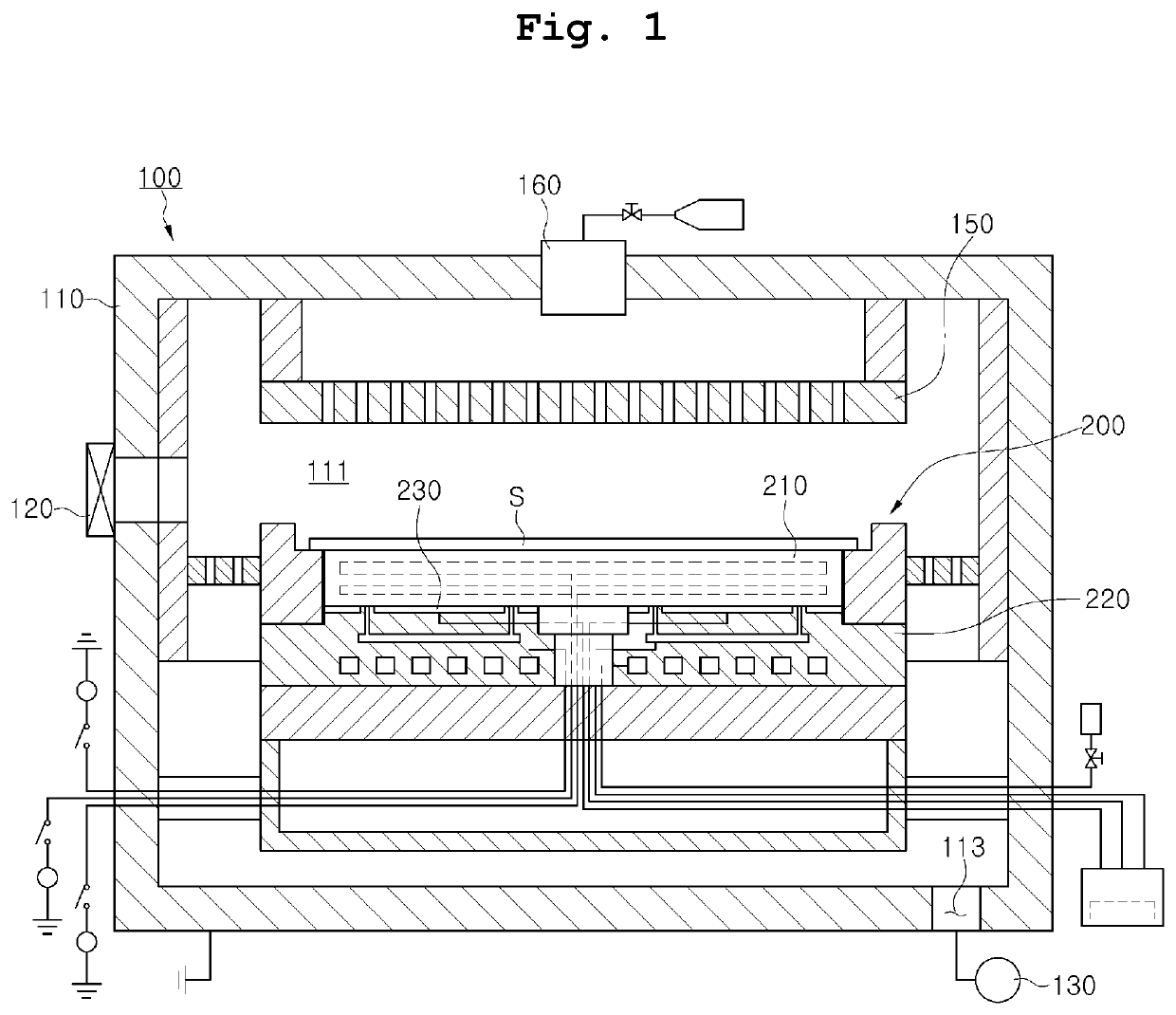
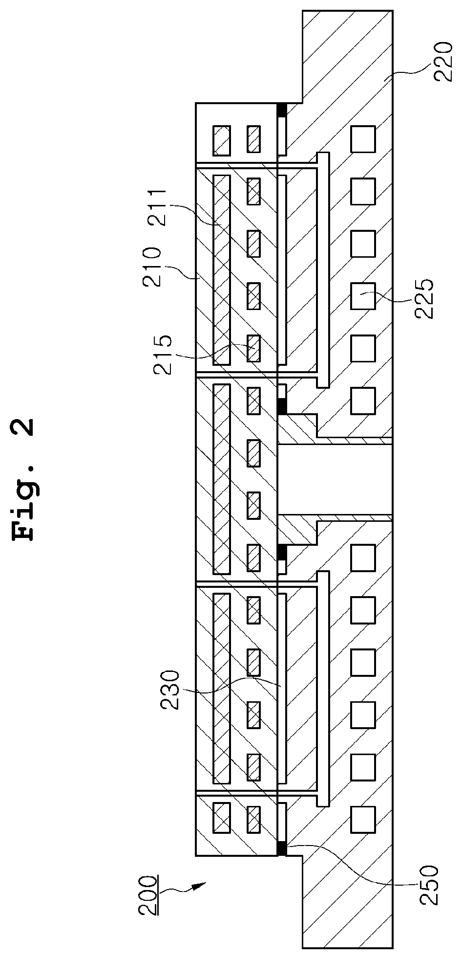
The present disclosure aims to prevent contaminants from being produced within a chamber due to the corrosion or etching of the bonding layer and to overcome the problem of a hot spot forming near the periphery of an electrostatic chuck. It also aims to prevent the bonding layer from being etched or decomposed little by little due to processing gas infiltrating into the bonding layer. Additionally, it allows for easy replacement of the sealing member while maintaining the bonding layer in the covered state, reducing the operating cost of the apparatus.

Problems solved by technology

Typically, a bonding material from which the bonding layer is made may be damaged by a processing gas or the like in a processing environment within a chamber.
Such damage in the bonding material may produce contaminants within the chamber, thereby significantly reducing the yield of the processing.
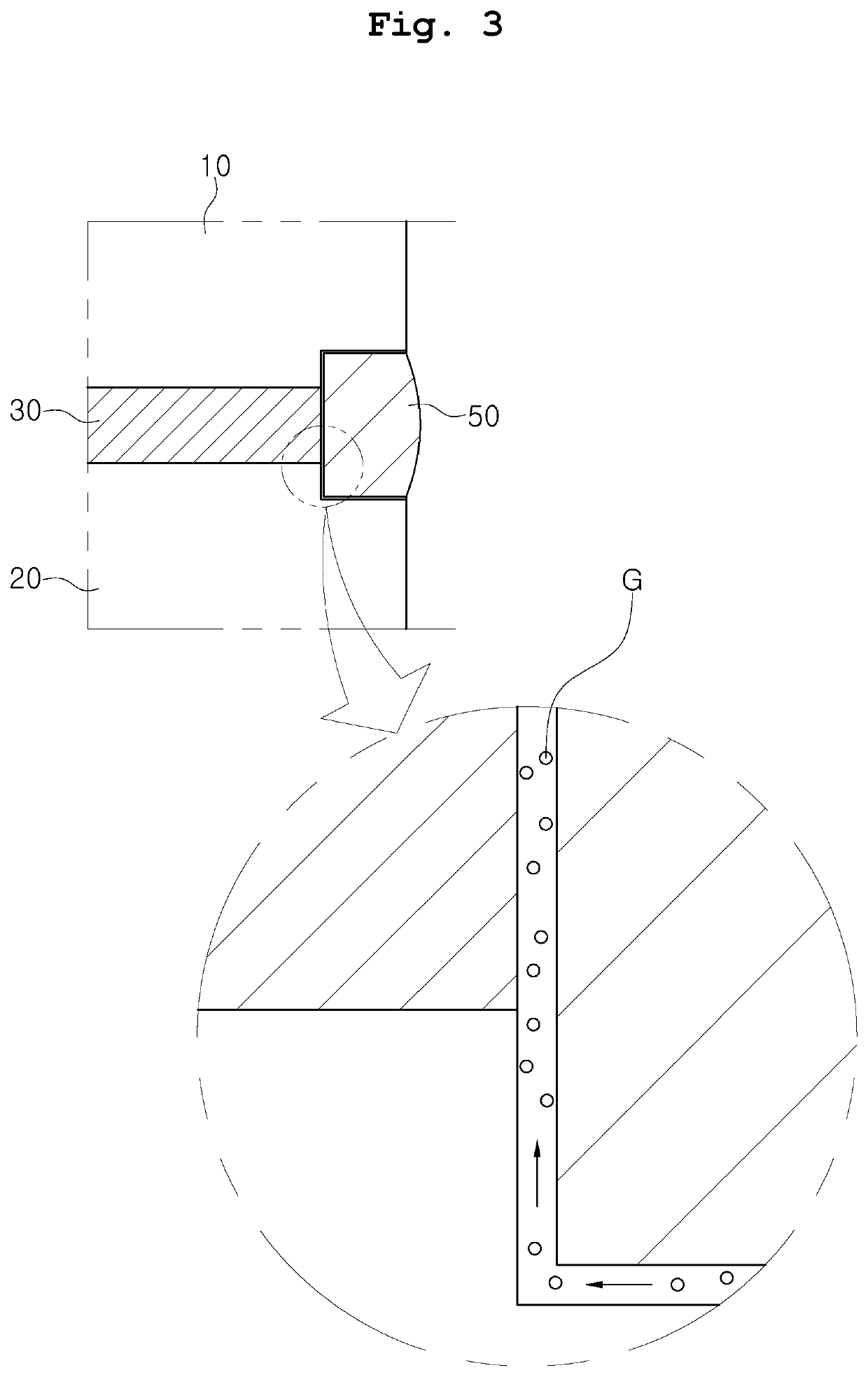
Consequently, there may be problems in that the periphery of the bonding layer may not be completely sealed, and a fine gap may be formed in the surface of the sealing member.
As this phenomenon is accumulated, a hot spot is formed in a location near the periphery of an electrostatic chuck, and the possibility that particles and contamination may occur is increased.

Method used


Image

  • Substrate processing apparatus and method of fabricating same
  • Substrate processing apparatus and method of fabricating same
  • Substrate processing apparatus and method of fabricating same

Examples


first embodiment

[0076]FIGS. 4A and 4B illustrate the substrate processing apparatus according to the present disclosure.

[0077]In FIG. 4A, a double sealing structure according to the present disclosure is provided around a bonding layer 330a, by which a chuck body 310a configured to attract and hold a substrate and a base plate 320a located below the chuck body 310a to support the chuck body 310a are bonded to each other.

[0078]More particularly, external edges of the chuck body 310a and the base plate 320a are stepped inward with respect to the bonding layer 330a, thereby defining a space between the chuck body 310a and the base plate 320a around the side surface of the bonding layer 330a. In addition, a covering member 351a is provided in a portion of the space between a chuck body 310a and a base plate 320a while surrounding the side surface of the bonding layer 330a, and a sealing member 355a is inserted into the space between the chuck body 310a and the base plate 320a around the side surface of...

second embodiment

[0090]FIG. 7 illustrates a flowchart of a method of fabricating the substrate processing apparatus according to the present disclosure.

[0091]Also in FIG. 7, a double-sealing structure 450 according to the present disclosure is provided around a bonding layer 430 bonding a chuck body 410 and a base plate 420. Here, the double-sealing structure 450 is configured such that a covering member 451 is coupled integrally to a sealing member 455 while surrounding a portion of the sealing member 455.

[0092]That is, the double-sealing structure may be configured such that all surfaces in contact with the space between the chuck body 410 and the base plate 420 and in contact with the sealing member 455 are surrounded by the covering member 451. In some cases, the covering member may be configured to occupy the entirety of the space between the chuck body 410 and the base plate 420, or at least a portion of the sealing member may be inserted into the covering member to be surrounded by the coveri...

third embodiment

[0100]That is, the third embodiment proposes the double-sealing structure 450a in which the sealing member 455a and the covering members 451a are integrated so that a fine gap occurring in the surface of the sealing member 455a in contact with the chuck body 410a and the base plate 420a is filled with a portion of the covering members 451a.

[0101]In the third embodiment as described above, in order to cover the bonding layer 430a by filling the fine gap occurring in the contact surface of the sealing member 455a with the covering members 451a, the fabrication process as described above with reference to FIG. 8 and FIGS. 9A to 9D are modified, so that the top portion and the bottom portion of the space defined by the chuck body 410a and the base plate 420a around the side surface of the bonding layer 430a is coated by injecting the covering material into the space, after the sealing material is inserted into the space so that the top portion and the bottom portion thereof are in cont...


PUM


Abstract

A substrate processing apparatus and a method of fabricating the same are proposed. A bonding layer, by which a chuck body and a base plate of an electrostatic chuck device are bonded, is completely covered using a double-sealing structure in which a covering member for preventing a processing gas from infiltrating into the bonding layer and a sealing member for preventing the bonding layer from being damaged are bonded to each other. The durability and the efficiency of the operation of the electrostatic chuck device are improved.

Description

CROSS REFERENCE TO RELATED APPLICATION[0001]The present application claims priority to Korean Patent Application No. 10-2020-0105066, filed Aug. 21, 2020, the entire contents of which are incorporated herein for all purposes by this reference.BACKGROUND OF THE INVENTIONField of the Invention[0002]The present disclosure relates generally to a substrate processing apparatus and a method of fabricating the same and, more particularly, to a technology for completely covering a bonding layer, by which a chuck body and a base plate of an electrostatic chuck (ESC) device are bonded, using a double-sealing structure in which a covering member for preventing a processing gas from infiltrating into the bonding layer and a sealing member for preventing the bonding layer from being damaged are bonded to each other, thereby improving the durability and the efficiency of the operation of the electrostatic chuck device.Description of the Related Art[0003]Generally, an electrostatic chuck device is...

Claims


Application Information

Patent Timeline
IPC IPC(8): H01J37/32H01L21/683
CPCH01J37/32724H01J2237/2007H01L21/6833H01L21/68785H01L21/68742H01L21/67109H01L21/67103H02N13/00B23Q3/15H01L21/67126
Inventor LEE, DONG MOKSUNG, JIN IL
Owner SEMES CO LTD
Learn More