Multiple sensor fusion engine
a multi-sensor and fusion engine technology, applied in the field of sensors, can solve the problems of inability to multiply and normalize the probability vectors of each radar subsystem, failure to yield accurate results, and difficult implementation, and achieve the effects of improving the discrimination of multi-sensor data, simple, fast and accura
- Summary
- Abstract
- Description
- Claims
- Application Information
AI Technical Summary
Benefits of technology
Problems solved by technology
Method used
Image
Examples
example 1
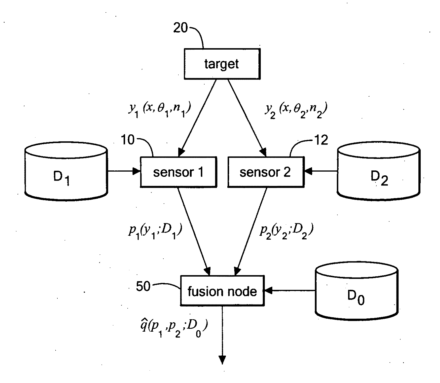
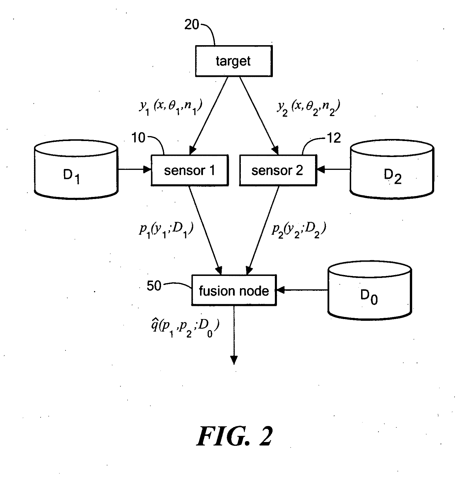
[0098]The first example is designed to show how much we can improve performance, relative to probability fusion. The setup is as follows: 2 features, 2 base classes, and 2 sensors wherein sensor 1 measures feature 1, and sensor 2 measures feature 2. There is no database mismatch and the sensors have the correct marginals. 10,000 training points were used. See FIG. 6.
[0099]As shown in FIG. 7A-7C the two base classes have equal covariances, but their means differ in both dimensions. The covariances are oriented at 45°, and have aspect ratios of 10:1, so the two features are very correlated. Because of the large correlation, and relatively small difference in the means, both sets of marginals have a lot of overlap. Because of the overlap, the results from simple probability fusion are very conservative, meaning that the estimated class probabilities are nearly uniformly distributed. If we had the features, we would get much better performance, because having both features makes it easi...
example 2
[0100]The second example is designed to show a more complicated case, with multiple sensors and database mismatch. The setup is as follows: 2 features, 5 base classes, and 2 sensors wherein sensor 1 measures feature 1, sensor 2 measures feature 1 and feature 2. The sensors have badly mismatched distributions. 10,000 training points were used. See FIG. 8.
[0101]As shown in FIGS. 9A-9C, the five base class distributions vary in spread and correlation. Sensor 1 measures feature 1, and has three classes. Sensor 2 measures both features, but has only two highly overlapping classes. There would be no clear way to do simple probability fusion. So, instead of using the probability fusion results for comparison, we'll use the results from the mapping derived from the least squares cost. In this case, mapping performs far better than declaring uniform probabilities (ignorance), substantially better than the least squares cost mapping, and very close to feature fusion. This shows that we can fu...
example 3
[0102]The third example is the same as the second case, except that now we only have sensor 2. The setup is as follows: 2 features, 5 base classes, and 1 sensor (measures both features). The sensor has badly mismatched distributions. 10,000 training points were used. See FIG. 10.
[0103]As shown in FIGS. 11A-11C, the sensor measures both features, and has the same distributions as sensor 2 in the previous example. This example is designed to test the algorithm when there is a lot of missing information. It is obvious that it is impossible to do as well as feature fusion, because the two sensor classes, will not give much insight into feature 1, since they only differ significantly along feature 2. A good algorithm will admit uncertainty when there is insufficient information. The worst thing you can do is to be overconfident, favoring some classes too strongly, while ruling out other classes. Overconfidence is much worse than ignorance. Overconfidence leads to performance that is wors...
PUM
 Abstract
Description
Claims
Application Information
 - R&D
- Intellectual Property
- Life Sciences
- Materials
- Tech Scout
- Unparalleled Data Quality
- Higher Quality Content
- 60% Fewer Hallucinations
Browse by: Latest US Patents, China's latest patents, Technical Efficacy Thesaurus, Application Domain, Technology Topic, Popular Technical Reports.
© 2025 PatSnap. All rights reserved.Legal|Privacy policy|Modern Slavery Act Transparency Statement|Sitemap|About US| Contact US: help@patsnap.com


