Moisture barrier breathing device

a technology of breathing device and moisture barrier, which is applied in the field of cleaning, can solve the problems of high friction of the window's dynamic sealing element, high and the higher the power and complexity of the driving lin

a technology of breathing device and moisture barrier, which is applied in the field of cleaning, can solve the problems of high friction of the window's dynamic sealing element, high and the higher the power and complexity of the driving lin

US20100071150A1Active Publication Date: 2010-03-25KERETH YEFIM

Image

  • Moisture barrier breathing device
  • Moisture barrier breathing device
  • Moisture barrier breathing device

Examples


Embodiment Construction

[0025]In the following description of some embodiments, identical components that appear in more than one figure or that share similar functionality will be referenced by identical reference symbols.

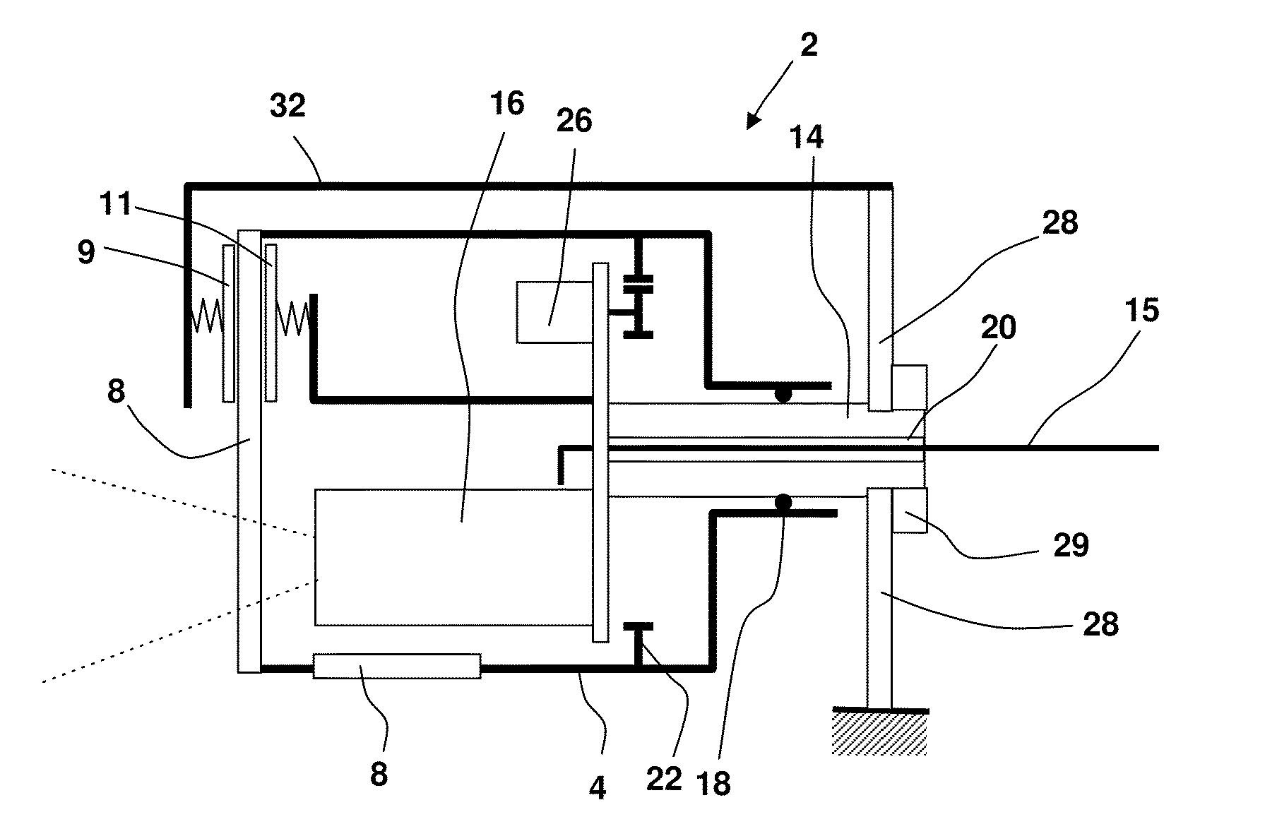
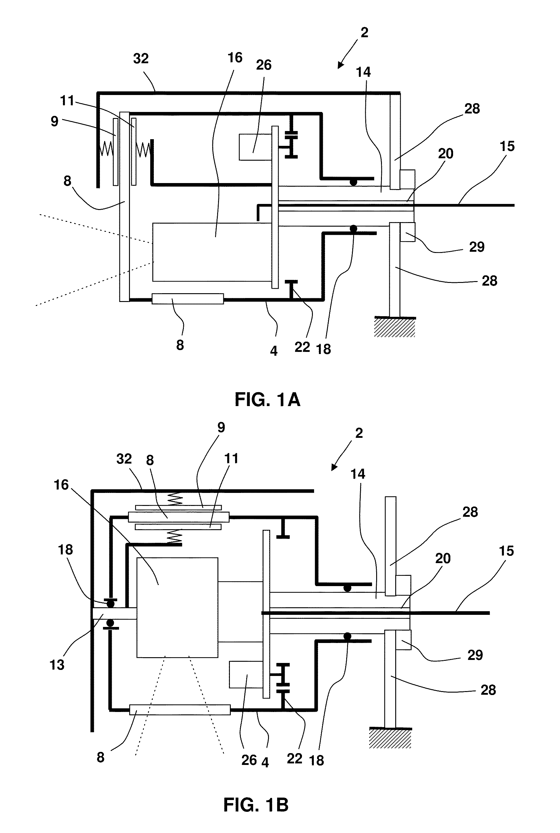
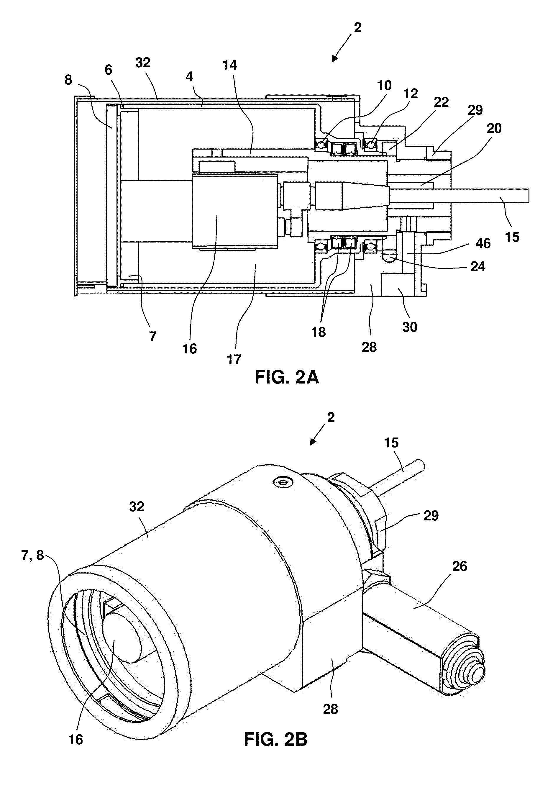
[0026]FIGS. 1A and 1B are simplified schematic side cross-sectional views of a cleaning assembly according to first and second embodiments of the invention, respectively, detailed views of which are shown in FIGS. 2A to 2E. As best seen in FIG. 1A, the cleaning assembly 2 comprises an enclosure 4 for accommodating therein an electro-optical device 16 (constituting an optical device). In FIG. 1A the optical device 16 is shown as having an optical axis parallel to a longitudinal axis of the enclosure 4. However, it may also be transverse thereto as shown in FIG. 1B. The enclosure 4 is adapted for rotation about a shaft 14 which supports the optical device. The shaft 14 is anchored to a stationary structure 28 via a flange nut 29 and includes a bore 20 for accommodating external electrical ...


PUM


Abstract

A cleaning assembly (2) for an optical device (16) includes a shaft (14) configured for supporting the optical device within an enclosure (4) that is adapted for rotation about the shaft. At least one first sealing element (18) is disposed between the shaft and a mating surface of the enclosure for preventing fluid leakage therethrough. At least one optically transparent window (8) is mounted in association with the enclosure (4), and at least one cleaning element (9, 11) is coupled to the shaft for cleaning a surface of the window (8). The cleaning assembly may include a moisture barrier in the form of a pressure-influenced member (58) such as a bellows (40) having a body of expandable and retractable-volume for containing air that diffuses therein, while equalizing pressure on opposite sides of the barrier.

Description

FIELD OF THE INVENTION[0001]The present invention relates to the cleaning of windows in optical instrument housings for removal of dirt and / or other contaminators.BACKGROUND OF THE INVENTION[0002]Rotatable windows that are automatically cleaned by a stationary cleaning element (e.g., wiper) without obscuring an observer's field-of-view are known per se. Reference is made, for example, to JP56169475, Dec. 26, 1981, which discloses a device for cleaning a TV camera comprising a rotating plate, a lower part of which is immersed in a water tank and which is rotated by an output shaft of a geared motor. A water-proof seal is to provided between the plate and a camera housing to avoid the water immersion in the camera housing. Current problems that militate against the implementation of rotatable windows and stationary cleaning elements for use with electro-optical assemblies include the high friction of the window's dynamic sealing element, commonly used to protect the instrument housing...

Claims


Application Information

Patent Timeline
25 Mar 2010
Publication
US20100071150A1
IPC
A47L7/00
CPC
B08B1/00; B08B1/02; B08B3/02; B08B5/02; G02B27/0006; G01N2021/151; G01N2021/152; G01N2021/158
Inventors
KERETH, YEFIM