Pneumatic power tool with air cooling system

a technology of pneumatic power tools and air cooling systems, which is applied in the direction of portable power-driven tools, percussive tools, drilling machines and methods, etc., can solve the problems of excessive heat in the gearbox not being allowed for a large continuous rating, oil leakage, and insufficient efficiency of gearing or angle gear cooling, etc., to improve the pneumatic torque/power delivery, and prolong the life of the tool

Inactive Publication Date: 2010-03-25
ATLAS COPCO TOOLS AB
View PDF14 Cites 0 Cited by
  • Summary
  • Abstract
  • Description
  • Claims
  • Application Information

AI Technical Summary

Benefits of technology

[0007]The object of the invention is to accomplish an improved pneumatic torque / power delivering tool in which air communication passages to, from and past the air motor and angle gear provide not only large enough flow areas for cooling but an optimum motor size in relation to the outer diameter of the tool housing. Another objective of the invention is to seal the gear chamber from exhaust air and thereby enabling durable lubrication possibilities which extends the lifetime of the tool. Another objective is to protect the ball bearings of the output tool shaft against overheating.

Problems solved by technology

In tools of the above type, there is always a problem to obtain an efficient enough cooling of the gearing or angle gear, due to heat generated during operation of the tool.
Excessive heat in the gearbox is not allowed for large continuous rating.
Problems that normally can occur are related to oil leakage due to excessive heat combined with wear of seals of the outgoing tool shaft.
Especially tools with an outgoing shaft rpm exceeding 12000 rpm, having a very high periphery seal contact speed; it is found that both angle gear and seals are overheated in applications where the tool is continuously used.
The primary problem to be solved is to minimise the temperature of the angle gearing during operation of the power tool.
A secondary problem is to seal the angle gear and improve lubrication possibilities by minimising lubricant leakage due to wear of seals at the outgoing tool shaft.
The problem is to obtain passages that do not interfere or enter the gear chamber but still have sufficient cooling effect.

Method used


Image

  • Pneumatic power tool with air cooling system
  • Pneumatic power tool with air cooling system
  • Pneumatic power tool with air cooling system

Examples


Embodiment Construction

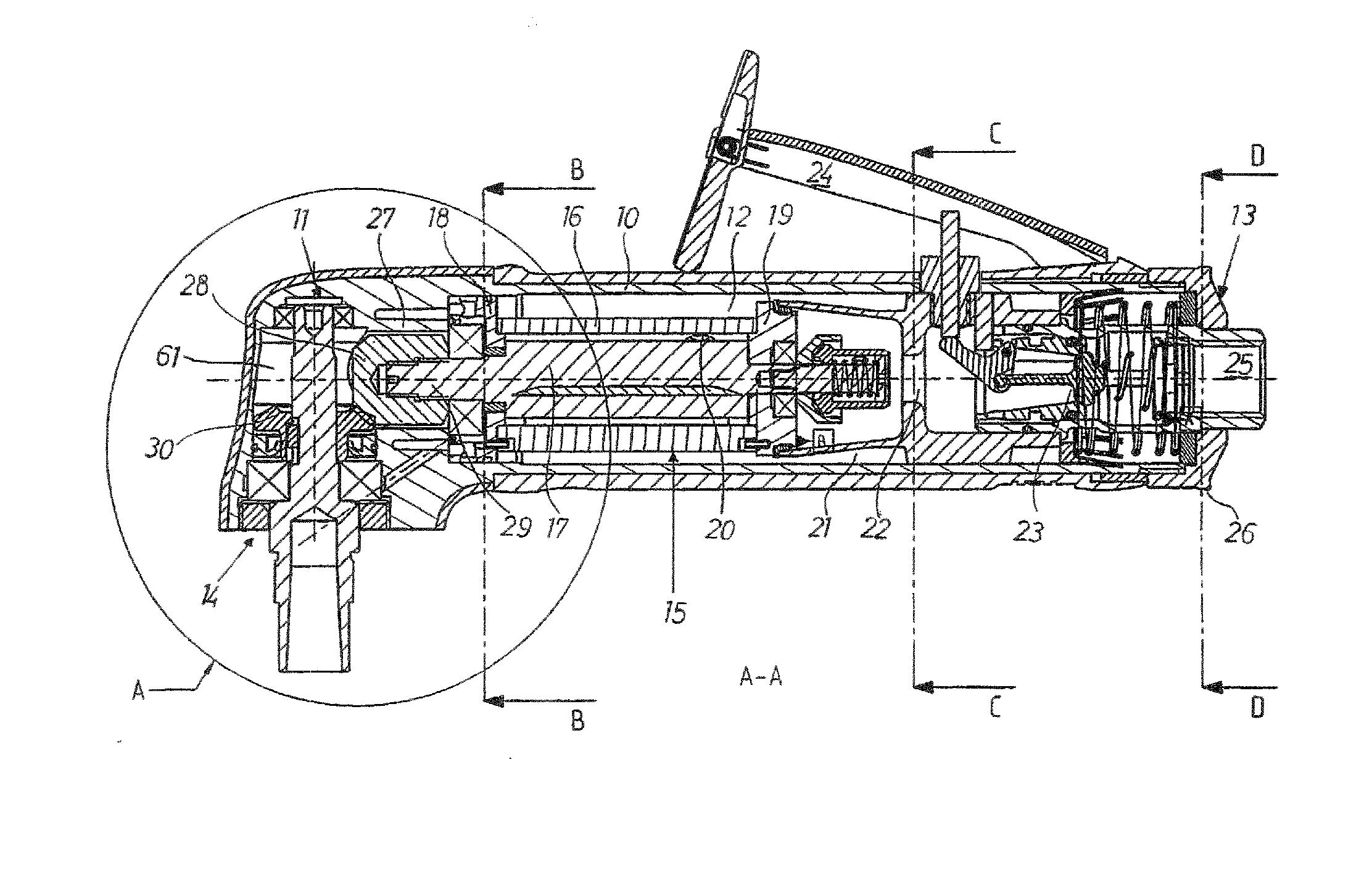
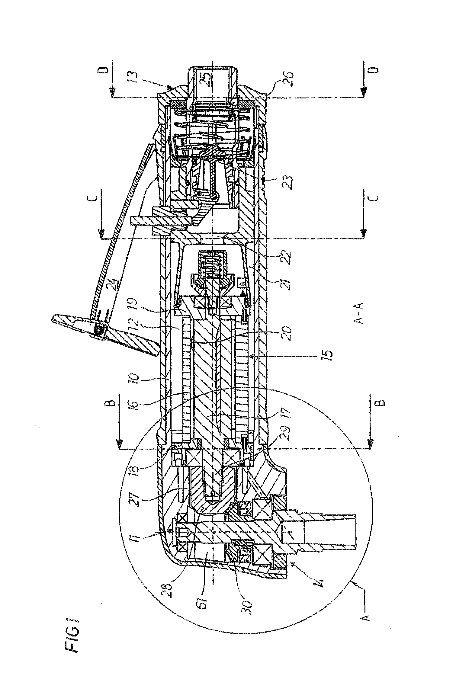
[0014]The tool shown in FIG. 1 comprises a housing 10 with a forward angle gear arrangement or angle gearing 11, a motor chamber 12, a rearward air outlet or exhaust section 13 and a forward air outlet or exhaust section 14.

[0015]The motor chamber 12 comprises a vane type rotation motor 15, including a cylinder 16 and a rotor 17. The motor is rigidly secured in the housing 10 and has a forward end wall 18 and a rearward end wall 19, which both are adapted to enable air passage. At its forward end, the rotor 17 is drivingly connected to the angle gearing 11. The motor cylinder 16 comprises a number of (radial) air communication openings which act as motor outlet openings 20. The outlet openings 20 communicate with both the rear part of the tool via rearward exhaust section 13 and with forward part of the tool via the forward exhaust section 14. The motor is of a conventional design, and since it is not in itself a part of the invention it is not described in further detail.

[0016]The ...


PUM


Abstract

A pneumatic air tool includes a housing with a forward angle gearing arranged in a gearing chamber, a motor chamber, a rear air outlet section and a forward air outlet section. The motor chamber includes a pneumatic motor with air communication openings, which communicate with both the rear air outlet section, and the forward air outlet section. A part of the outlet air is ducted through the forward air outlet section including a circular groove in the housing which form part of a cooling chamber. The walls of the groove form together an enlarged heat transferring surface by which the heat generated in the angle gearing is efficiently transferred to the cold exhaust air from the motor passing through the cooling chamber. By communicating exhaust air through the cooling chamber there is obtained an efficient cooling of the angle gearing while maintaining favorable outer dimensions of the housing.

Description

BACKGROUND OF THE INVENTION[0001]This invention relates to pneumatically powered tools for abrasive or fastening related work.[0002]In particular, the invention concerns a pneumatic power tool which comprises a tool housing including a forward angle gear arrangement, a rearward motor chamber including a pneumatic motor, air inlet and outlet passages extending from the rear end of the tool, and an air outlet at the forward end of the tool.[0003]The combination of minimal tool exterior body area and demand for increased maximum torque / power deliverance sets high demand on the angle gear. In tools of the above type, there is always a problem to obtain an efficient enough cooling of the gearing or angle gear, due to heat generated during operation of the tool. Excessive heat in the gearbox is not allowed for large continuous rating. Problems that normally can occur are related to oil leakage due to excessive heat combined with wear of seals of the outgoing tool shaft. Especially tools w...

Claims


Application Information

Patent Timeline
Patent Type & Authority Applications(United States)
IPC IPC(8): E21B19/16
CPCB25F5/008
Inventor ELMQVIST, KARL STEFAN
Owner ATLAS COPCO TOOLS AB
Why Eureka
Try Eureka