Machine tool, working fluid supply apparatus, and working fluid

a technology of working fluid supply and machine tool, which is applied in the direction of manufacturing tools, metal rolling arrangements, metal-working machine components, etc., can solve the problems of reducing the usable life of tools, shortened tool lifetime, and reduced tool life, so as to shorten the lifetime of tools and improve productivity. , the effect of significantly increasing the tool li

Active Publication Date: 2015-05-05
MAKINO MILLING MASCH CO LTD
View PDF18 Cites 1 Cited by
  • Summary
  • Abstract
  • Description
  • Claims
  • Application Information

AI Technical Summary

Benefits of technology

[0012]Heat resistant steel, such as nickel alloy or stainless steel for which machining temperature tends to be high, and aluminum alloy and titanium alloy which tend to be fused and adhered to a cutting edge of a tool, reduce usable life of a tool. In machining of aluminum alloy or titanium alloy, chips generated by processing tend to fuse and adhere to a cutting edge of a tool, and thus induce chipping and lead to reduction of tool life. In processing of these metals, a water soluble working fluid obtained by mixing water and oil in a prescribed ratio is used to lower the processing temperature and suppress fused adhesion of metal in order to extend usable lifetime of the tool. Water and oil that have no co-solubility are used in the water soluble working fluid, so that an emulsifier is added to ensure homogeneous dispersion of oil particles in water. The water soluble working fluid containing an emulsifier is generally referred to as an emulsion type water soluble working fluid. As described in Patent Literature 1, an emulsifier is an anionic surfactant, a non-ionic surfactant, or mixture of them. Since an emulsifier has an effect of reducing surface tension, it can advantageously disperse oil in water so as to form a homogeneous working fluid. On the other hand, there is a problem that, when the emulsifier is used in processing of metals such as titanium alloy, nickel alloy, or aluminum alloy, tool lifetime tends to be shortened. There is also a problem that, since tap water containing hydroxide ion is used as water in the working fluid, hydroxide ion tends to be bound to the surface of workpiece immediately after machining, and this obstructs adhesion of oil particles on the metal surface.
[0013]The present invention has been done in order to resolve above-described problems. Thus, it is an object of the present invention to provide a machine tool, a working fluid supply apparatus, and a working fluid capable of extending lifetime of a tool when processing metal such as titanium alloy, nickel alloy or aluminum alloy by using a water soluble working fluid.

Problems solved by technology

Heat resistant steel, such as nickel alloy or stainless steel for which machining temperature tends to be high, and aluminum alloy and titanium alloy which tend to be fused and adhered to a cutting edge of a tool, reduce usable life of a tool.
In machining of aluminum alloy or titanium alloy, chips generated by processing tend to fuse and adhere to a cutting edge of a tool, and thus induce chipping and lead to reduction of tool life.
On the other hand, there is a problem that, when the emulsifier is used in processing of metals such as titanium alloy, nickel alloy, or aluminum alloy, tool lifetime tends to be shortened.
There is also a problem that, since tap water containing hydroxide ion is used as water in the working fluid, hydroxide ion tends to be bound to the surface of workpiece immediately after machining, and this obstructs adhesion of oil particles on the metal surface.

Method used


Image

  • Machine tool, working fluid supply apparatus, and working fluid
  • Machine tool, working fluid supply apparatus, and working fluid
  • Machine tool, working fluid supply apparatus, and working fluid

Examples


first embodiment

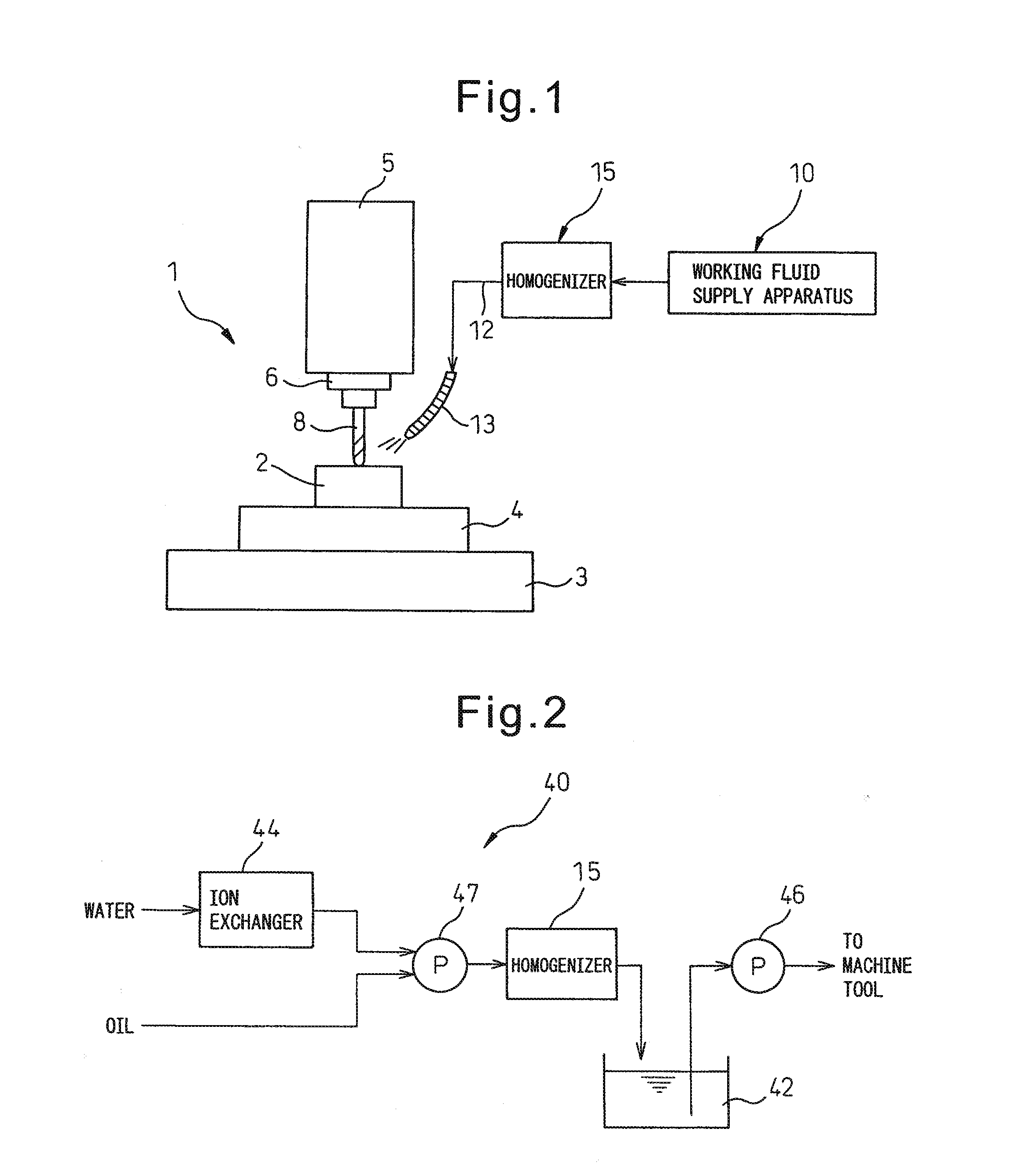
[0036]Next, referring to FIG. 2, a working fluid supply apparatus according to the present invention will be described. Unlike the working fluid supply apparatus 10 shown in FIG. 1, the working fluid supply apparatus 40 of the present embodiment includes a homogenizer 15 and a tank 42 for storing the homogenized working fluid. As homogenizer 15, the pressure type homogenizer shown in FIG. 4 as described above can be used. In the homogenizer 15 of the present embodiment, deionized water ion-exchanged by an ion exchanger 44 and oil are introduced. In place of tap water containing hydroxide ion, deionized water containing no hydroxide ion is used so that bonding of hydroxide ion to the metal surface of the workpiece immediately after processing can be suppressed. Therefore, oil is attached directly to the surface of the workpiece, and the lubricating action of the working fluid is enhanced. As a result, chips are prevented from adhering by fusion to the tool, and the occurrence of chip...

second embodiment

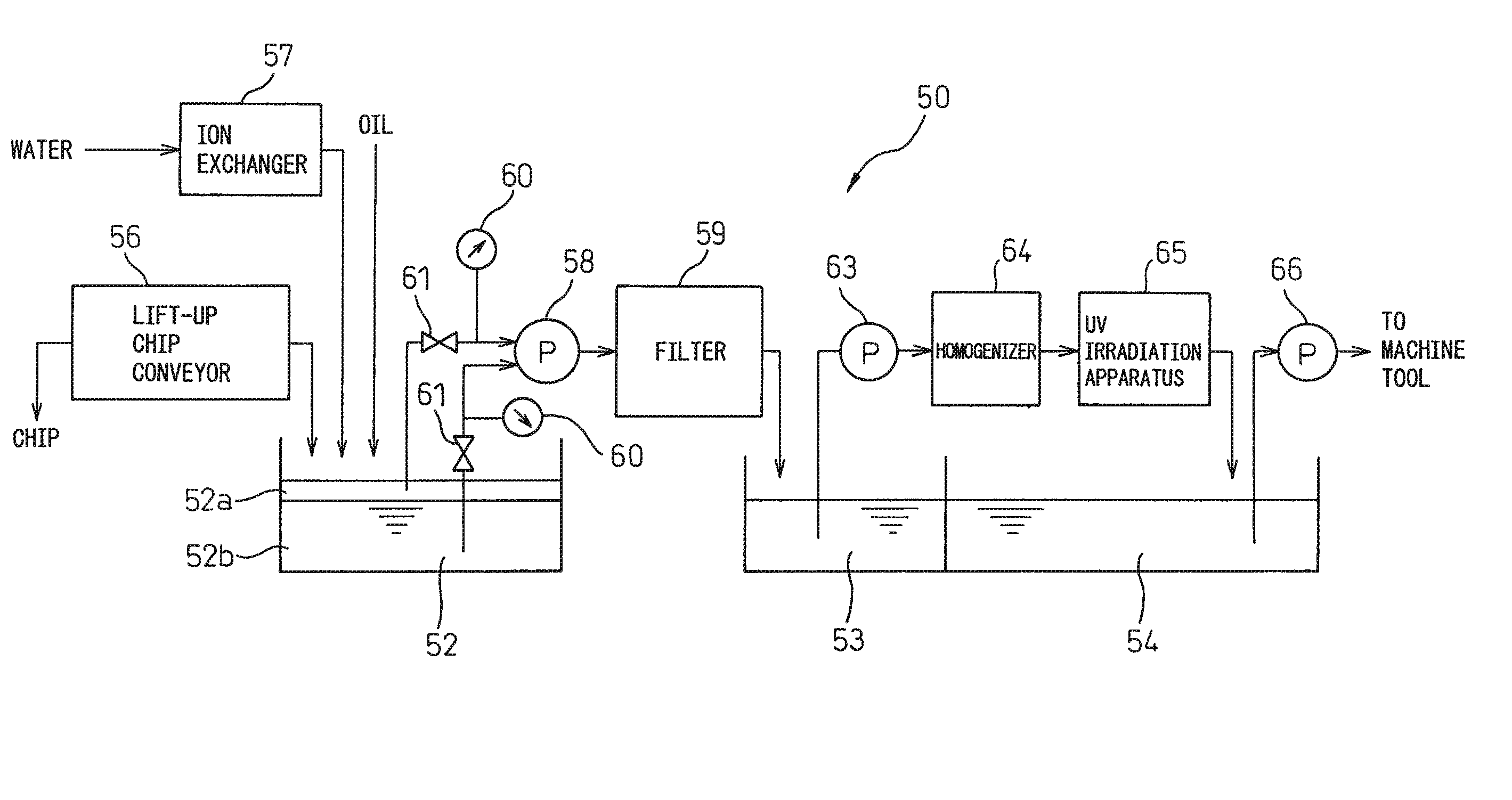
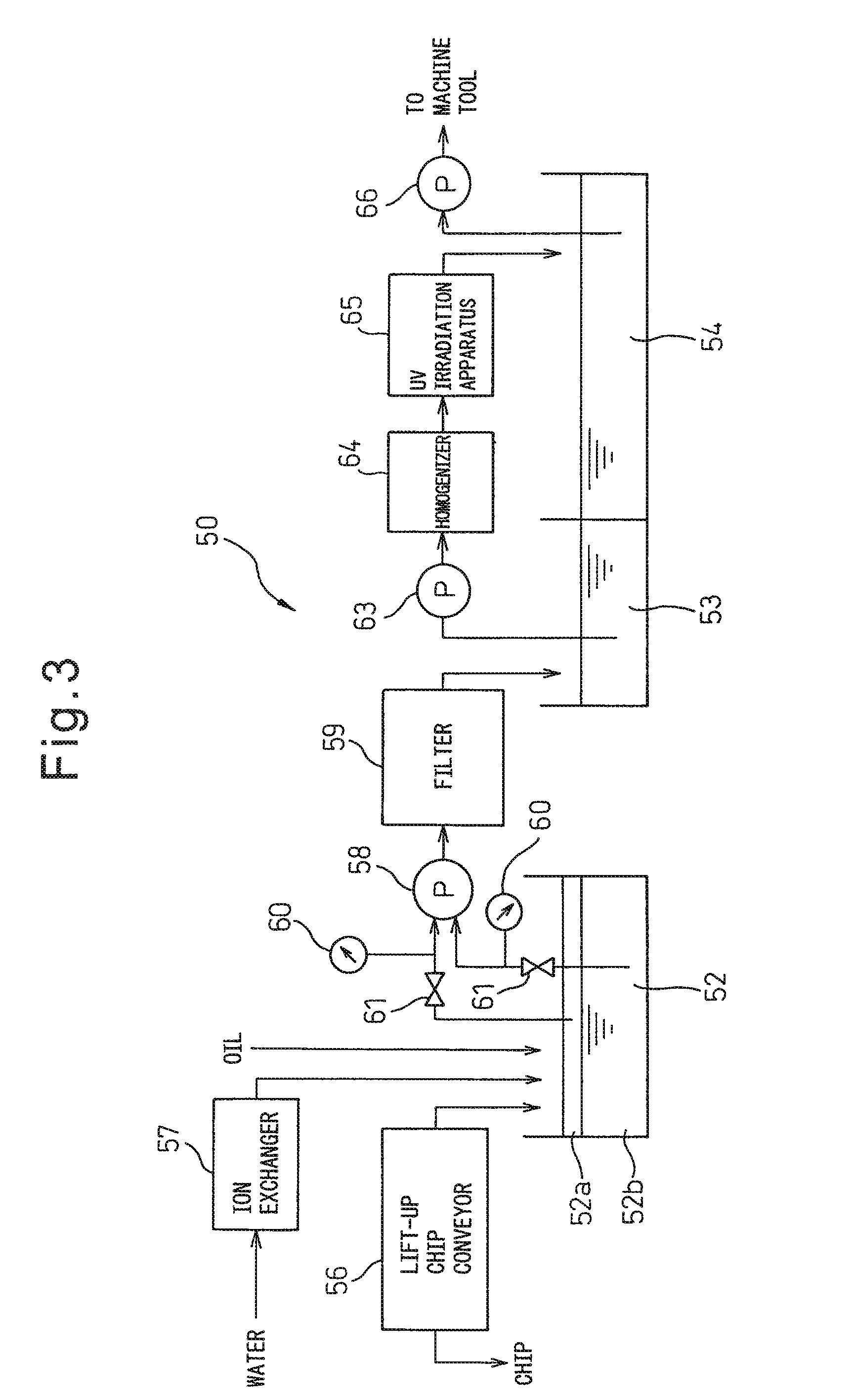
[0037]FIG. 3 is a view showing the working fluid supply apparatus of the present invention. A working fluid supply apparatus 50 of this embodiment includes a primary tank 52 for recovering the working fluid used in the processing, and can be advantageously used with a machine tool that is automatically run for a long time. The working fluid is conveyed from the machine tool together with chips, and separated into chips and the working fluid by a lift-up chip conveyor 56. The separated working fluid is stored together with deionized water for replenishment ion-exchanged in an ion exchanger 57 and replenished new oil in the primary tank 52. Commercially available deionized water or deionized water generated in advance by other means may be used. Liquid from the upper layer 52a and lower layer 52h of the liquid mixture of the water and oil in the primary tank 52 is respectively extracted with a pump 58, and is supplied to a filter 59. As the filter 59, a rotary cyclone filter may be us...


PUM

PropertyMeasurementUnit
mean particle diameteraaaaaaaaaa
diameteraaaaaaaaaa
diameteraaaaaaaaaa

Abstract

A machine tool (1) for processing a workpiece (2) by relative movement of a tool (18) with respect to the workpiece (2), including a homogenizer (15) into which water and oil are taken to disperse oil homogeneously in water, a working fluid produced in homogenizer (15) being supplied to a work area for processing of the workpiece.

Description

TECHNICAL FIELD[0001]The present invention relates to a machine tool, a working fluid supply device, and a working fluid for machine processing of a workpiece, such as cutting, grinding and honing of a workpiece while supplying a working fluid.BACKGROUND ART[0002]A working fluid supplied during machine processing of a workpiece has various actions as described below. The working fluid has lubricating action in which the working fluid permeates between a workpiece and a tool or between a tool and chips generated by processing to reduce friction at the boundary surface, anti-fusion action in which the working fluid prevents generation of built-up edge or fusion of chips to a tool, and cooling action in which the working fluid absorbs friction heat generated between a workpiece and a tool or between a tool and chips or heat generated in shearing of metal, or the working fluid cools a workpiece or a tool. These actions of the working fluid vary according to the type of the working fluid...

Claims


Application Information

Patent Timeline
Patent Type & Authority Patents(United States)
IPC IPC(8): B23Q11/12B21B45/02B23Q11/10
CPCB23Q11/1061Y10T409/304032
Inventor TAGASHIRA, KOHSUKEIKEDA, SHIN-ICHIYAMASAKI, MASAYA
Owner MAKINO MILLING MASCH CO LTD
Why Eureka
Try Eureka