Coating layer for cutting tools

a technology of coating layer and cutting tool, which is applied in the direction of superimposed coating process, natural mineral layered products, instruments, etc., can solve the problems of reducing the life of the coating layer during machining, cvd and pvd, and the resistant coating layer may be easily damaged, so as to prolong the tool life and improve the cutting performance

Inactive Publication Date: 2015-04-07
KORLOY
View PDF22 Cites 0 Cited by
  • Summary
  • Abstract
  • Description
  • Claims
  • Application Information

AI Technical Summary

Benefits of technology

[0021]With respect to a coating layer for cutting tools according to the present invention, since surface residual stress of the coating layer becomes a compressive stress state after coating by using a chemical vapor deposition (CVD) method, a typical blasting treatment or mixed use of a physical vapor deposition (PVD) method may not be required, and thus, the lifetime of the tools may be extended by a simplified process.
[0022]Also, since a cover layer according to the present invention not only provides distinctiveness from products of other makers but also include 75 at % or more of aluminum, aluminum may form aluminum oxide by being combined with oxygen in the air during machining, and thus, an additional improvement of cutting performance may be expected because the cover layer may also partially act as a wear-resistant layer.

Problems solved by technology

However, with respect to a stress state of the foregoing typical chemical vapor deposition (CVD) coating layer for cutting tools, since surface residual stress is maintained in a tensile stress state up to the alumina layer as shown in FIG. 1, the wear-resistant coating layer may be easily damaged due to the effect of residual stress, and thus, lifetime of the coating layer may be decreased during machining.
However, a separate process may be added due to the blasting process, and a process of mixed use of the CVD and PVD method may not only be inconvenience but adhesion between the CVD layer and the PVD layer may also be poor, and thus, physical properties of the coating layer may deteriorate.

Method used


Image

  • Coating layer for cutting tools
  • Coating layer for cutting tools
  • Coating layer for cutting tools

Examples


Embodiment Construction

[0030]Hereinafter, the present invention will be described in detail with reference to the accompanying drawings. The invention may, however, be embodied in many different forms and should not be construed as being limited to the embodiments set forth herein; rather, these embodiments are provided so that this disclosure will be thorough and complete, and will fully convey the concept of the invention to those skilled in the art.

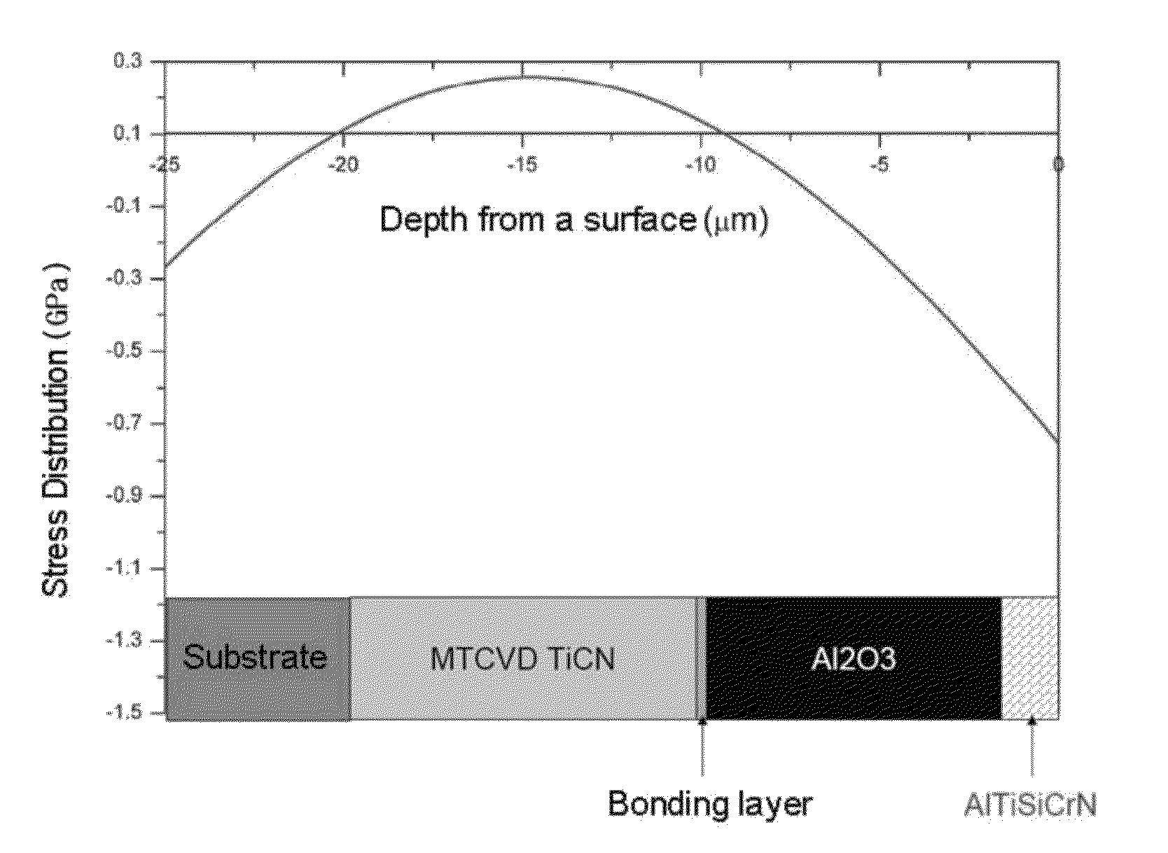
[0031]A coating layer for cutting tools according to the present invention is formed on a surface of a parent material by using a chemical vapor deposition (CVD) method and includes an alumina layer formed of an α-phase, disposed on the parent material and composed of a composite structure having a columnar crystal structure and an equiaxed crystal structure mixed therein, and a cover layer formed of AlxTiySizCrwN (herein, x+y+z+w=1, x≧0.75, y≧0.2, 0≦z≦0.06, 0≦w≦0.08) and disposed on the alumina layer.

[0032]The coating layer for cutting tools according to th...


PUM

PropertyMeasurementUnit
thicknessaaaaaaaaaa
pressureaaaaaaaaaa
temperatureaaaaaaaaaa

Abstract

Provided is a coating layer for cutting tools, as a hard coating layer stacked and formed in the sequence of a TiN layer, a TiCN layer, a bonding layer, an alumina (Al2O3) layer, and a cover layer from the bottom by using a chemical vapor deposition (CVD) method on a parent material, able to improve cutting performance, because surface residual stress of the coating layer may be maintained in a compressive stress state by adjusting a composition of the cover layer without using a separate additional process, such as a blasting operation, or a mixed process of CVD and physical vapor deposition (PVD), and simultaneously the cover layer may also be used as a wear-resistant layer.

Description

CROSS REFERENCE TO PRIOR APPLICATIONS[0001]This application is a National Stage Patent Application of PCT International Patent Application No. PCT / KR2011 / 005014 (filed on Jul. 8, 2011) under 35 U.S.C. §371, which claims priority to Korean Patent Application No. 10-2011-0053757 (filed on Jun. 3, 2011), which are all hereby incorporated by reference in their entirety.TECHNICAL FIELD[0002]The present invention relates to a hard coating layer formed on a cemented carbide parent material, and more particularly, to a hard coating layer, as a hard coating layer stacked and formed in the sequence of a TiN layer, a TiCN layer, a bonding layer, an alumina (Al2O3) layer, and a cover layer from the bottom by using a chemical vapor deposition (CVD) method on the parent material, able to improve cutting performance, because surface residual stress of the coating layer may be maintained in a compressive stress state through the cover layer having a composition different from that of a TiN / TiCN lay...

Claims


Application Information

Patent Timeline
Patent Type & Authority Patents(United States)
IPC IPC(8): C23C14/06B26D7/00C23C16/34C23C16/40C23C28/04C23C30/00
CPCB26D7/00C23C16/34C23C16/403C23C30/005C23C28/042C23C28/044Y10T428/265B23B27/14C23C16/12C23C16/44
Inventor CHO, SEONG WOOKIM, HAN SUNGLEE, DONG YOULHAN, DAE SUKSEO, YOUNG HOAHN, SEOUN YOUNGPARK, DONG BOK
Owner KORLOY
Why Eureka
Try Eureka