Method of controlling feed axes in machine tool, and machine tool performing machining by using the method of controlling feed axes

a technology of machine tools and feed axes, which is applied in the direction of computer control, program control, instruments, etc., can solve the problems of complicated calculation formulas and difficulty in obtaining a sufficient tool lifetime, and achieve the effect of suppressing the effect of the runout amount of the tool and increasing the tool lifetim

Active Publication Date: 2016-04-28
OKUMA CORP
View PDF4 Cites 1 Cited by
  • Summary
  • Abstract
  • Description
  • Claims
  • Application Information

AI Technical Summary

Benefits of technology

[0005]In view of the above, an object of the present invention is to provide a method of controlling feed axes in a machine tool and the machine tool capable of obtaining a control amount in which maximum values of actual machining allowances are averaged by simple calculation and capable of increasing the lifetime of the tool.
[0014]According to the present invention, the runout amounts of the tool in respective axes directions corresponding to the tool position (rotation angle) are corrected in the feed axes side during machining not by complicated calculation method requiring time but by simple calculation. Therefore, the control amounts whereby the maximum values of actual machining allowances are averaged are obtained. Accordingly, the machining can be performed while suppressing the effect of the runout amounts of the tool, which increases the lifetime of the tool.

Problems solved by technology

However, it is difficult to obtain a sufficient tool lifetime as the runout amount does not become minimum with the average value.
However, since the value is converged in this method by repeatedly performing calculation for obtaining the maximum solution, it is necessary to execute the method a plurality of times and it takes time, and a calculation formula becomes complicated.

Method used


Image

  • Method of controlling feed axes in machine tool, and machine tool performing machining by using the method of controlling feed axes
  • Method of controlling feed axes in machine tool, and machine tool performing machining by using the method of controlling feed axes
  • Method of controlling feed axes in machine tool, and machine tool performing machining by using the method of controlling feed axes

Examples


Embodiment Construction

[0021]Hereinafter, an embodiment of the present invention will be explained with reference to the drawings.

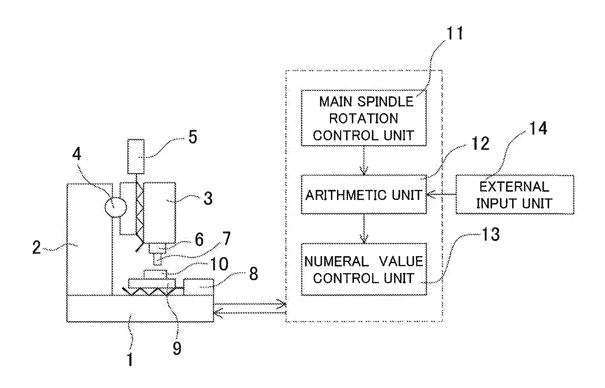
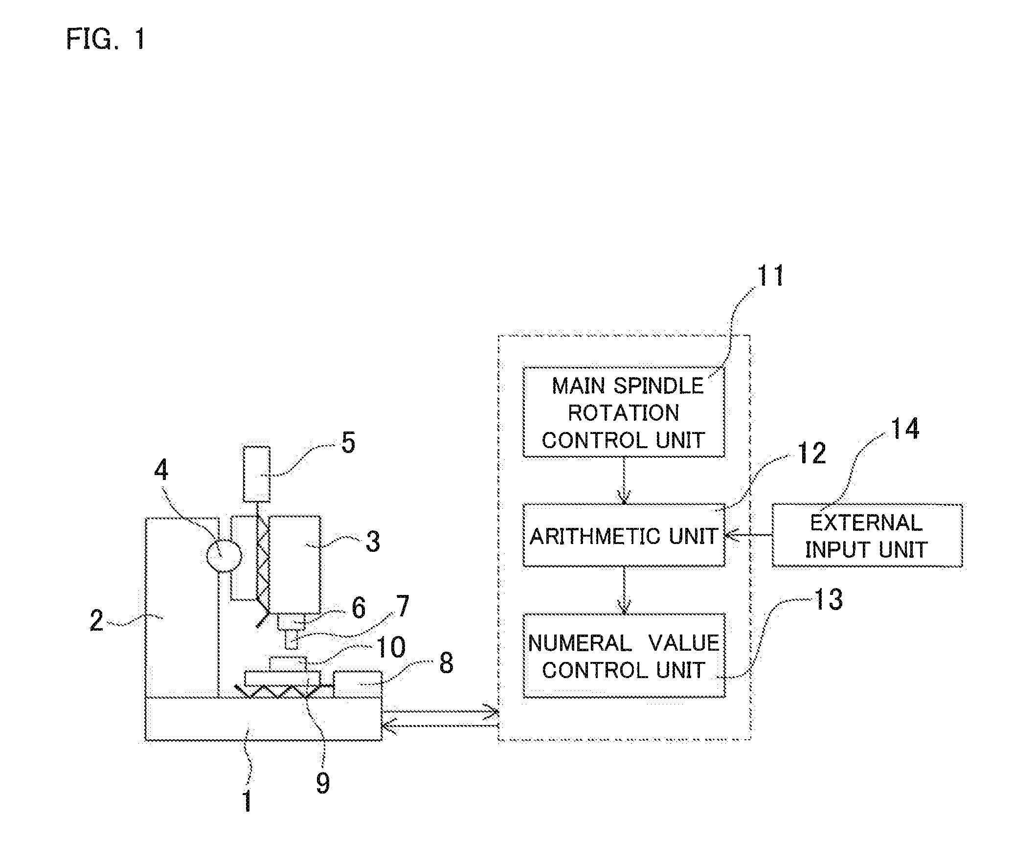
[0022]FIG. 1 is a structural view showing an example of a machine tool which executes a method of controlling feed axes according to the present invention. In the drawing, 1 denotes a bed, 2 denotes a column. A spindle head 3 is provided in front of the column 2 so as to be controlled to move in an X-axis direction and a Z-axis direction by an X-axis control unit 4 and a Z-axis control unit 5. A tool 7 is attached to a main spindle 6 provided under the spindle head 3 so as to face downward. A table 9 which can be controlled to move in a Y-axis direction by a Y-axis control unit 8 is provided above the bed 1, and a workpiece 10 can be fixed on the table 9.

[0023]A control system of the machine tool includes a main spindle rotation control unit 11 controlling a rotation speed of the main spindle 6, an arithmetic unit 12 calculating control amounts of the feed axes (respective cont...


PUM

PropertyMeasurementUnit
Riaaaaaaaaaa
heightsaaaaaaaaaa
tool lifetimeaaaaaaaaaa

Abstract

Maximum values of actual machining allowances of a workpiece in respective cutting flutes are averaged by control amounts of respective cutting flutes calculated by an arithmetic unit. The arithmetic unit converts the calculated control amounts into an amount in each axis direction and subtracts the value from a feed axis command value in an NC program stored in a storage unit. Then, a numeral value control unit performs machining by controlling respective feed axes based on the subtracted feed axis command value.

Description

BACKGROUND OF THE INVENTION[0001]This application claims the benefit of Japanese Patent Application Number 2014-218475 filed on Oct. 27, 2014, the entirety of which is incorporated by reference.FIELD OF THE INVENTION[0002]The present invention relates to a method of controlling feed axes in a machine tool in order to suppress generating of chatter vibration and chipping of a tool by controlling the feed axes in consideration of runout amounts in cutting edges of the tool during machining by the machine tool, particularly, during heavy cutting of a hard-to-cut material such as titanium alloy. The present invention also relates to a machine tool performing cutting by using the method of controlling feed axes.DESCRIPTION OF RELATED ART[0003]When the hard-to-cut material is machined by milling, a tool, to which detachable cutting edges called “Throw-away” or “Insert” are attached, is used for reducing machining costs. The heights of the attached cutting edges are not uniform in this too...

Claims


Application Information

Patent Timeline
Patent Type & Authority Applications(United States)
IPC IPC(8): B23Q15/12G05B19/404
CPCG05B19/404B23Q15/12B23C2222/88B23C2250/16B23Q17/0904G05B2219/50318
Inventor INAGAKI, HIROSHI
Owner OKUMA CORP
Why Eureka
Try Eureka