
Electrical system using phase-shifted carrier signals and related operating methods

a phase-shifted carrier signal and electric system technology, applied in the direction of electric energy management, electric devices, dynamo-electric motors/converters starters, etc., can solve the problems of limiting the size and cost of the capacitor in the inverter, the inability to shrink the size and cost of the capacitor, and the inability to find capacitors with the proper capacitance and current rating

Inactive Publication Date: 2010-03-25
GM GLOBAL TECH OPERATIONS LLC
View PDF35 Cites 78 Cited by
  • Summary
  • Abstract
  • Description
  • Claims
  • Application Information

AI Technical Summary

Benefits of technology

The patent describes an automotive drive system that includes a three-phase motor and an inverter module. The motor has two sets of windings with opposite magnetic polarities, and the inverter module has two sets of phase legs that are connected to each set of windings. The technical effect of this design is improved performance and efficiency of the automotive drive system.

Problems solved by technology

One of the changes involves the power usage and complexity of the various electrical systems within automobiles, particularly alternative fuel vehicles, such as hybrid, electric, and fuel cell vehicles.
However, the power sources (e.g., batteries) used in such applications provide only direct current (DC) power.
Often, the capacitor current limits the ability to shrink the size and cost of the capacitor in the inverter.
This generally results in use of a larger capacitor than necessary because it is difficult to find a capacitor with the proper capacitance and current rating.
This, in turn, limits the ability to reduce the size, weight, and cost of the power inverter module.

Method used


Image

  • Electrical system using phase-shifted carrier signals and related operating methods
  • Electrical system using phase-shifted carrier signals and related operating methods
  • Electrical system using phase-shifted carrier signals and related operating methods

Examples


Embodiment Construction

[0020]The following detailed description is merely illustrative in nature and is not intended to limit the embodiments of the subject matter or the application and uses of such embodiments. As used herein, the word “exemplary” means “serving as an example, instance, or illustration.” Any implementation described herein as exemplary is not necessarily to be construed as preferred or advantageous over other implementations. Furthermore, there is no intention to be bound by any expressed or implied theory presented in the preceding technical field, background, brief summary or the following detailed description.

[0021]The following description refers to elements or nodes or features being “coupled” together. As used herein, unless expressly stated otherwise, “coupled” means that one element / node / feature is directly or indirectly joined to (or directly or indirectly communicates with) another element / node / feature, and not necessarily mechanically. Thus, although the schematics shown here...


PUM

PropertyMeasurementUnit
volumeaaaaaaaaaa
DC energyaaaaaaaaaa
magnetic polarityaaaaaaaaaa

Abstract

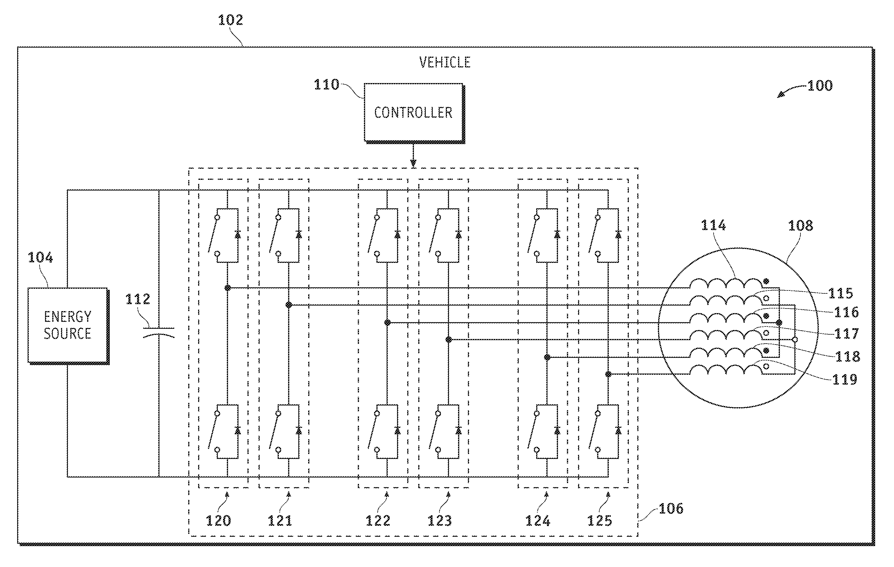
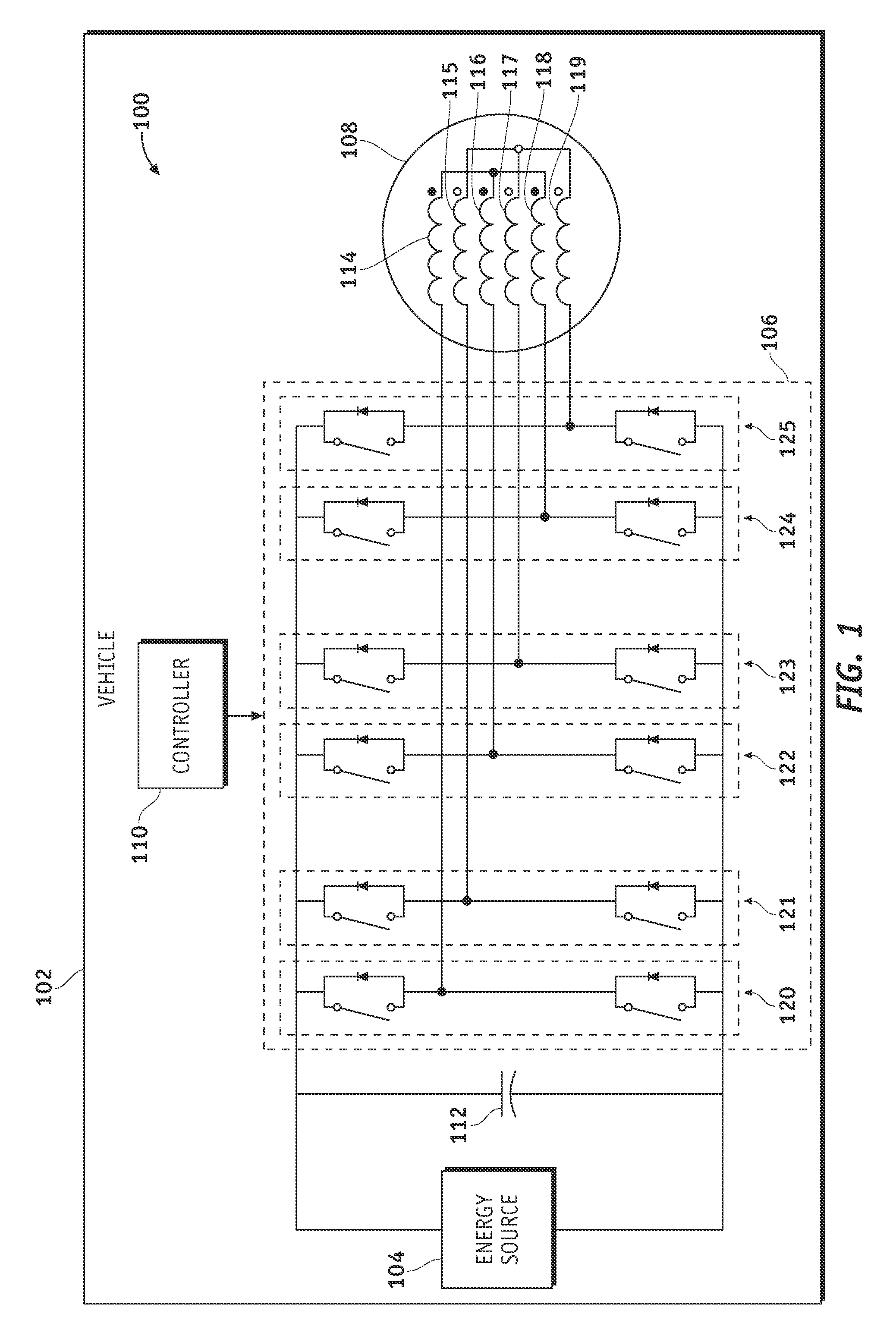
An automotive drive system and methods for making the same are provided. The system includes a three-phase motor and an inverter module. The three-phase motor includes a first set of windings each having a first magnetic polarity; and a second set of windings each having a second magnetic polarity that is opposite the first magnetic polarity. The first set of windings being electrically isolated from the second set of windings. The inverter module includes a first set of phase legs and a second set of phase legs. Each one of the first set of phase legs is coupled to a corresponding phase of the first set of windings, and each one of the second set of phase legs is coupled to a corresponding phase of the second set of windings.

Description

CROSS-REFERENCE TO RELATED APPLICATION[0001]This is a continuation-in-part of application Ser. No. 12 / 236,172, filed Sep. 23, 2008.STATEMENT REGARDING FEDERALLY SPONSORED RESEARCH OR DEVELOPMENT[0002]The United States government has a paid-up license in this invention and the right in limited circumstances to require the patent owner to license others on reasonable terms as provided by the terms of contract number DE-FC26-07NT43123 awarded by the United States Department of Energy.TECHNICAL FIELD[0003]Embodiments of the subject matter described herein relate generally to vehicle drive systems, and more particularly, embodiments of the subject matter relate to electric and / or hybrid vehicles having an inverter drive system.BACKGROUND[0004]In recent years, advances in technology, as well as ever evolving tastes in style, have led to substantial changes in the design of automobiles. One of the changes involves the power usage and complexity of the various electrical systems within auto...

Claims


Application Information

Patent Timeline
Patent Type & Authority Applications(United States)
IPC IPC(8): B60K1/00H02K23/36H02P6/14H02K11/00H05K13/00
CPCB60K1/00Y10T29/49002B60L15/02B60L2210/46B60L2220/12B60L2220/58H02K3/28H02K11/0073H02M7/5387H02M7/53871H02P5/74H02P25/22H02P27/08Y02T10/641Y02T10/644Y02T10/7005Y02T10/7241B60L11/1803B60L50/51H02K11/33Y02T10/64Y02T10/70Y02T10/72
Inventor WELCHKO, BRIAN A.CAMPBELL, JEREMY B.
Owner GM GLOBAL TECH OPERATIONS LLC
Learn More