System and method for controlling power transfer across an inductive power coupling

a power transfer and inductive power technology, applied in the direction of battery overheat protection, safety/protection circuit, instruments, etc., can solve the problems of low power inductive electrical power transmission system over extended surfaces, dangerous socket holes, and unsuitable for high-energy systems

Active Publication Date: 2010-03-25
POWERMAT TECHNOLOGIES
View PDF102 Cites 120 Cited by
  • Summary
  • Abstract
  • Description
  • Claims
  • Application Information

AI Technical Summary

Problems solved by technology

Nevertheless, socket holes are dangerous and children do sometimes manage to insert pencils, pins and other objects into socket holes, sometimes with fatal results.
Water can also cause shorting and may result in electrocution.
Low power inductive electrical power transmission systems over extended surfaces are not new.
It will be appreciated however, that extended base units such as Hui's charging surface which transmit energy continually approximately uniformly over the whole area of the unit, are not suitable for use with high energy systems.
But being harder to spot than conventional power outlets has its disadvantages.
The problem of locating such sockets is particularly acute where the power outlets are behind a concealing surface such as a desk top or wall, and the positions thereof are adjustable over a large area.
Locating mobile source ‘hotspots’ or sockets is particularly problematic in high power systems where no extended power transmission surface is provided.
Moreover, a high power primary coil produces a large oscillating magnetic field.
Where there is no secondary coil to focus the power, the oscillating magnetic field causes high energy electromagnetic waves to be transmitted which may be harmful to bystanders.
In contrast to low power systems, such as Hui's charging surface, where excess heat may be readily dissipated, uncoupled high power primary coils and their surroundings may become dangerously hot.
Nevertheless due to the lack of connecting wires in inductive power couplings, conductive communication channels are not practical.

Method used


Image

  • System and method for controlling power transfer across an inductive power coupling
  • System and method for controlling power transfer across an inductive power coupling
  • System and method for controlling power transfer across an inductive power coupling

Examples


first embodiment

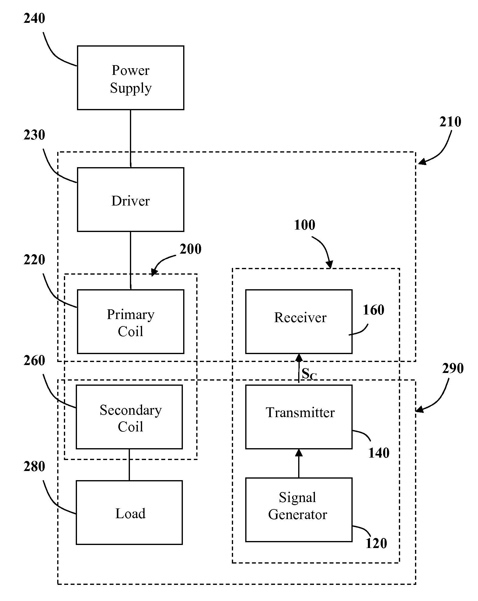
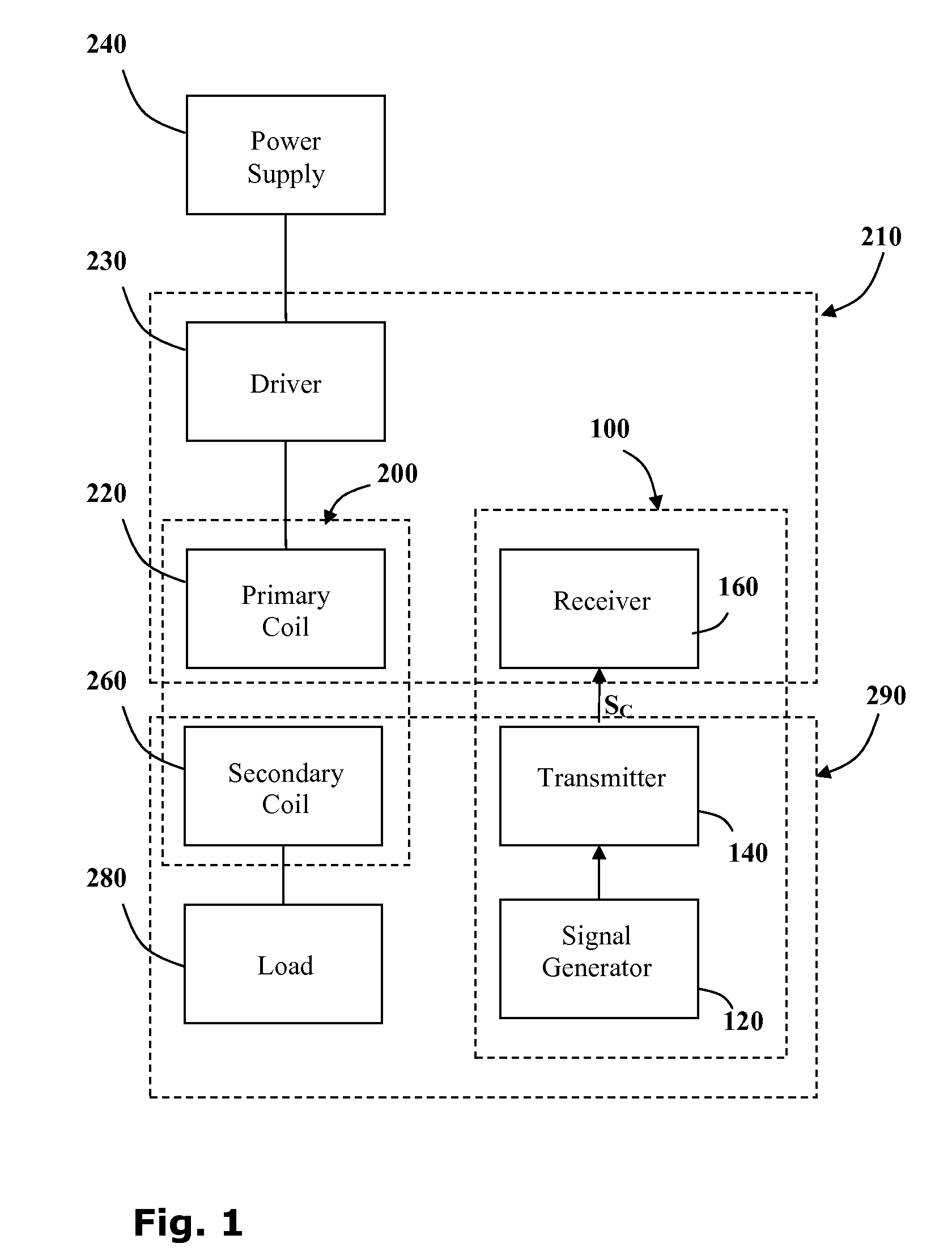
[0097]Reference is now made to FIG. 1 showing a block diagram of the main elements of an inductive power coupling 200 incorporating a signal transfer system 100 according to the invention.

[0098]The inductive power coupling 200 consists of a primary inductive coil 220 and a secondary inductive coil 260. The primary coil 220 is wired to a power supply 240 typically via a driver 230 which provides the electronics necessary to drive the primary coil 220. Driving electronics may include a switching unit providing a high frequency oscillating voltage supply, for example. The secondary coil 260 is wired to an electric load 280.

[0099]When the secondary coil 260 is brought into proximity with the primary coil 220, the pair of coils forms an inductive couple and power is transferred from the primary coil 220 to the secondary coil 260. In this way a power outlet 210 may provide power to an electric device 290.

[0100]The signal transfer system 100 comprises: a signal generator 120, for generatin...

third embodiment

[0134]As an example of the signal transfer system 100 (FIG. 1), with reference to FIG. 3, according to the invention, a signal transfer system 3100 may be integrated into a contactless inductive power coupling system 3200 where power is inductively transmitted from a jack unit 3212 to a plug unit 3292 galvanically isolated therefrom. A transmission circuit 3140 embedded in the plug unit 3292 may be used to transmit control signals SC to a receiver circuit 3160 in the jack 3212. Thus once the primary L1 and secondary L2 coils are aligned, control signals may be passed between the plug 3292 and jack 3212 units with no need to align additional components such as optocouplers, and the like.

[0135]Where a contactless plug 3292 is used, for example to power a portable computer 3290 having on-board power cells 3280, the signal transfer system 3100 may be used to detect the presence of the load 3290 producing a detection signal SDL and then to provide the jack 3212 with signals relating to t...


PUM

PropertyMeasurementUnit
inductive poweraaaaaaaaaa
frequencyaaaaaaaaaa
poweraaaaaaaaaa

Abstract

A signal transfer system for controlling power transfer across an inductive power coupling. A transmission circuit associated with an inductive power receiver is configured to transmit a control signal to a reception circuit associated with an inductive power outlet. The transmission circuit includes an ancillary load and a switching unit for modulating power drawn by a secondary inductive coil according to the control signal. The reception circuit is configured to monitor power provided to a primary inductive coil thereby detecting the modulated control signal. The signal transfer system may be used to regulate the power supplied by the inductive coupling and to detect the presence of the secondary coil.

Description

CROSS-REFERENCE TO RELATED APPLICATIONS[0001]This application is a continuation of PCT application Serial No. PCT / IL2008 / 000401 filed Mar. 23, 2008, which claims the benefit of U.S. provisional application Ser. Nos. 60 / 907,132 filed Mar. 22, 2007, 60 / 935,847 filed Sep. 4, 2007, 61 / 006,076 filed Dec. 18, 2007, 61 / 006,106 filed Dec. 19, 2007, 61 / 006,488 filed Jan. 16, 2008 and 61 / 006,721 filed Jan. 29, 2008.FIELD OF THE INVENTION[0002]The present invention is directed to providing devices, a system and method for controlling power transfer across an inductive power coupling.BACKGROUND[0003]For safety, the power supplying side of a conductive couple is generally the female part, and does not have bare conductive elements protruding therefrom. A plug coupled to the device is the corresponding male part with bare pins. The size of the pins and holes are such that a child cannot insert his or her fingers thereinto. In high quality sockets, an earth connection is provided, and, only when a...

Claims


Application Information

Patent Timeline
Patent Type & Authority Applications(United States)
IPC IPC(8): H01F38/00H02M1/00
CPCH02J5/005H02J7/025H01F38/14Y02B70/1433Y02B70/1491H02M2001/0058H02M3/3376H02J7/00045H02J7/00712H02J7/007192Y02B70/10H02J50/402H02J7/00309H02J50/80H02J50/90H02J50/70H02J50/10H02J50/20H02J50/40H02M1/0058G01V3/08
Inventor AZANCOT, YOSSIBEN-SHALOM, AMIRGREENWALD, OOLAROFE, ARIK
Owner POWERMAT TECHNOLOGIES
Why Eureka
Try Eureka