Liquid container, method of filling liquid into liquid container, and remanufacturing method of liquid container

a liquid container and liquid technology, applied in the direction of valve operating means/releasing devices, functional valve types, transportation and packaging, etc., can solve the problems of complex and advanced internal structure of ink cartridges, inability to achieve efficient ink refilling, and complicated ink flow path structur

Active Publication Date: 2010-03-25
SEIKO EPSON CORP
View PDF9 Cites 43 Cited by
  • Summary
  • Abstract
  • Description
  • Claims
  • Application Information

AI Technical Summary

Benefits of technology

[0012]The liquid filling method according to this aspect of the invention fills the liquid into the area other than the specific section adjoining to and directly communicating with the bubble trap flow path in the pathway of the liquid. Even if the shavings of the liquid container produced in the course of formation of the inlet are mixed into the liquid inside the liquid container, the location of shaving contamination is not adjacent to the bubble trap flow path and thus effectively prevents the shavings mixed into the liquid from reaching the bubble trap flow path. This arrangement desirably prevents the blockage of the bubble trap flow path or the increasing flow resistance of the bubble trap flow path due to accumulation of the shavings in the bubble trap flow path. This arrangement also prevents the occurrence of edges in the cylindrical flow paths due to accumulation of the shavings in the bubble trap flow path and thereby maintains the liquid backflow control mechanism. The liquid filling method of this aspect ensures the liquid refill without damaging the functions of the liquid container. In the specification thereof, the terminology ‘specific section adjoining to and directly communicating with the bubble trap flow path’ includes any of various chambers and flow paths for the liquid defined by the inner walls in the pathway of the liquid.
[0016]The liquid container according to this aspect of the invention has the effects discussed above in the liquid filling process. Sealing the inlet with the sealing member does not damage the functions of the liquid container. The liquid refill through the inlet is easily performed many times by the simple removal of the sealing member.

Problems solved by technology

This structure interferes with the ink flowing into a pathway between the ink reservoir assembly and the ink outlet and accordingly does not attain the efficient ink refill.
The ink refill technique of the above cited reference is not simply applicable to ink cartridges of the complicated and advanced internal structure.
For example, in an ink cartridge equipped with a sensor unit including an ink sensor that utilizes a piezoelectric element to detect the level of remaining ink, the ink flow path structure is especially complicated to avoid false detection of the ink sensor caused by migration of the air into the sensor unit.
Formation of the through hole naturally produces some shavings of the cartridge casing, which may be mixed into the ink stored in the ink cartridge and may damage the functions of the ink cartridge.
This problem is not characteristic of the ink cartridge for the printer but is commonly found in diversity of liquid containers used for supplying a liquid to a liquid consuming device, for example, a liquid container for supplying a metal-containing liquid material to an injection device designed to inject the liquid material onto a semiconductor substrate and thereby form an electrode layer on the semiconductor substrate.

Method used


Image

  • Liquid container, method of filling liquid into liquid container, and remanufacturing method of liquid container
  • Liquid container, method of filling liquid into liquid container, and remanufacturing method of liquid container
  • Liquid container, method of filling liquid into liquid container, and remanufacturing method of liquid container

Examples


modification 2

[0095]C-2. Modification 2

[0096]The ink cartridge remanufacturing process of the embodiment first fills ink into the upstream of the buffer chamber 440 (step S630) and subsequently fills ink into the downstream of the buffer chamber 440 (step S650). This sequence is, however, not essential but may be reversed. Filling ink in the downstream prior to filling ink in the upstream may cause the shavings entering through the inlet hole 720b to move on the flow of the injected ink to the downstream. In this case, the shavings move away from the bubble trap flow path 400 and may be discharged from the liquid feeder 50. This accordingly enhances the effect of preventing the shavings from reaching the bubble trap flow path 400. It is preferable to fill ink with air suction out of the cartridge body 10, for example, by inserting a needle into the liquid feeder 50 and sucking the air with a vacuum pump. This further facilitates the discharge of the shavings and further enhances the above effect....

modification 3

[0097]C-3. Modification 3

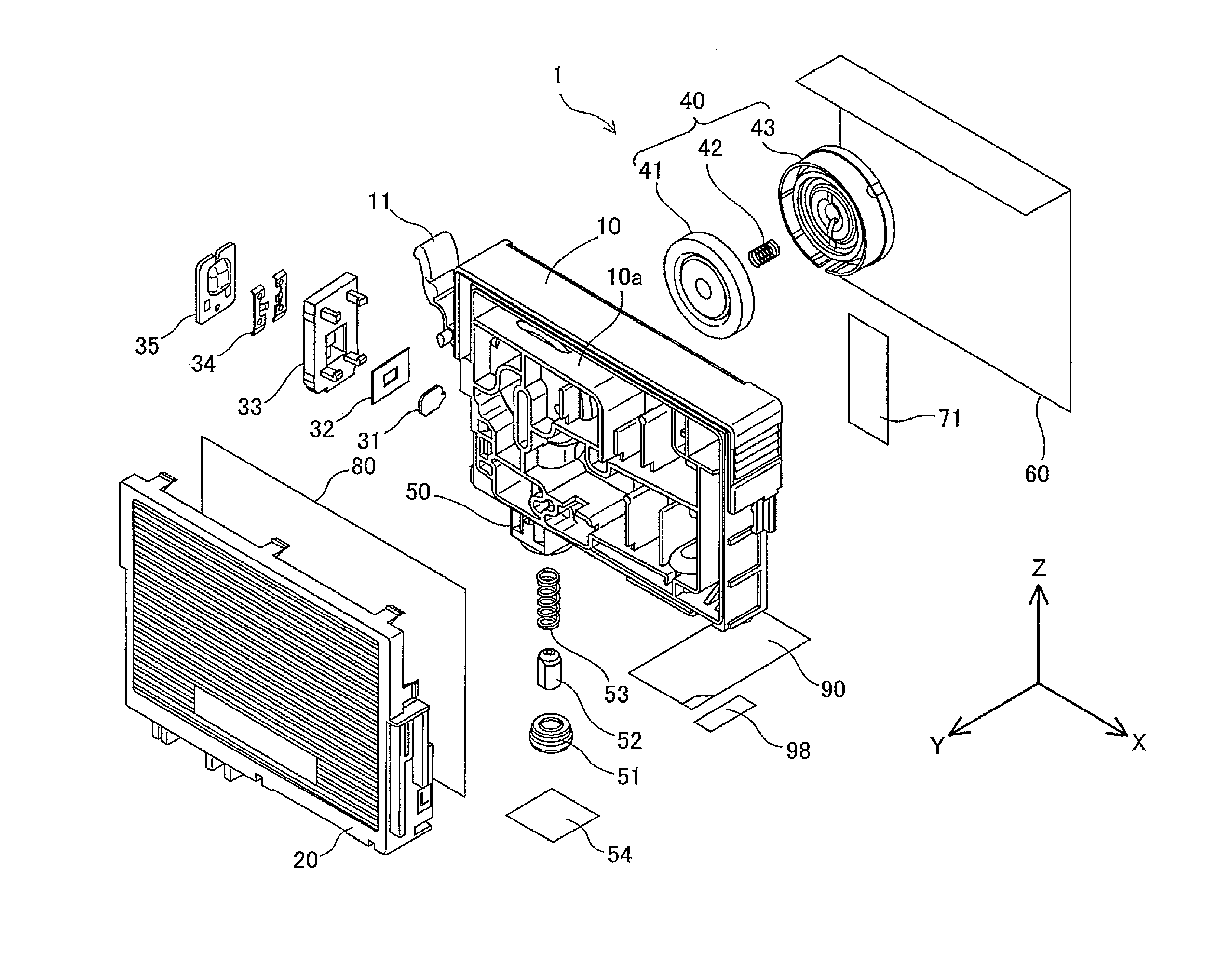
[0098]The ink cartridge remanufacturing process of the embodiment forms the inlet holes 720a and 720b connecting with the buffer chamber 440 in the inlet formation area 710 on the left lateral face of the cartridge body 10. The location of inlet formation is, however, not restricted to this area. An inlet may be formed on the film 80 applied on the front face of the cartridge body 10 as shown by a hatched area in FIG. 18A. An inlet may otherwise be formed in a specific area 910 on the outer surface film 60 applied on the rear face of the cartridge body 10 as shown by a hatched area in FIG. 18B.

modification 4

[0099]C-4. Modification 4

[0100]In the embodiment and its modified examples discussed above, the ink cartridge remanufacturing process injects ink into the buffer chamber 440. The location of ink injection is, however, not restricted to the buffer chamber 440 but may be the tank chamber 370. In one modified structure, an inlet may be formed on the film 80 applied on the front face of the cartridge body 10 as shown by a hatched area in FIG. 19A. In another modified structure, an inlet may be formed in a specific area 920 on the outer surface film 60 applied on the rear face of the cartridge body 10 as shown by a hatched area in FIG. 19B.

[0101]In still another modified structure, an inlet may be formed in a specific area 930 on the right lateral face of the cartridge body 10 to be pierced through the air chamber 350 or the air chambers 340 and 320 as shown in FIG. 20A. In this case, the inlet may pass through the right lateral face of the cartridge body 10 and the inner wall defined by...


PUM


Abstract

According to one aspect of the invention, a remanufacturing method of a liquid container forms an inlet in a certain area, for example, a buffer chamber, other than a specific section including liquid reservoirs and flow paths adjoining to and directly communicating with a bubble trap flow path in the liquid container. In the state of closing a liquid feeder and opening an air open structure, the remanufacturing method injects a liquid through the inlet to fill a space in the upstream of the inlet with the liquid. In the state of opening the liquid feeder and closing the air open structure, the remanufacturing method injects the liquid through the inlet to fill a space in the downstream of the inlet with the liquid. The remanufacturing process seals the inlet after completion of the injection of the liquid. This arrangement enables the liquid to be refilled into the liquid container without damaging the functions of the liquid container.

Description

CROSS-REFERENCE TO RELATED APPLICATION[0001]This present application claims priority from Japanese application JP 2008-169071 A filed on Jun. 27, 2008, the contents of which are hereby incorporated by reference into this application.BACKGROUND[0002]1. Field of the Invention[0003]The present invention relates to a liquid refill technique of refilling a liquid into a liquid container structured to store the liquid, which is to be supplied to a liquid consuming device.[0004]2. Description of the Related Art[0005]In ink-jet printers, in response to detection of out-of-ink with consumption of ink stored in an ink cartridge, the used ink cartridge is generally replaced with a new ink cartridge. As ink cartridges are recycled, more active approaches for the more efficient use of resources have been demanded and discussed. One approach refills ink into the used ink cartridge. Some techniques have been proposed for ink refill in the ink cartridge as disclosed in, for example, Japanese Patent...

Claims


Application Information

Patent Timeline
Patent Type & Authority Applications(United States)
IPC IPC(8): B41J2/175F16K31/12
CPCB41J2/17506Y10T137/7287
Inventor WANIBE, AKIHISAISHIZAWA, TAKUSHINADA, SATOSHIMIYAJIMA, CHIAKI
Owner SEIKO EPSON CORP
Why Eureka
Try Eureka