Television receiver with a TV phone function

a technology of tv phone and receiver, which is applied in the field of tv receiver set, can solve the problems of user labor, time-consuming and troublesome operations, and user labor, and achieve the effects of reducing labor for such operations, increasing usability for users, and saving user labor

Active Publication Date: 2010-03-25
MAXELL HLDG LTD
View PDF10 Cites 77 Cited by
  • Summary
  • Abstract
  • Description
  • Claims
  • Application Information

AI Technical Summary

Benefits of technology

[0021]With the above-stated arrangement, it is possible to provide a TV receiver with increased usability for users. For example, video image displaying for a videophone call is performed using the display screen and loudspeaker module which are inherently used for digital TV broadcast programs; so, it is possible for a user to start a phone call and finish the call without having to move from a place at which s / he is enjoying a digital TV broadcast program. This saves the user's labor for such moving action. Additionally, upon completion of the phone call, the decoder and encoder are automatically rendered inoperative without requiring the user to perform manual operations. This results in a decrease in labor for such operations. It is also possible to prevent a calling party from becoming aware of the digital TV broadcast program which is watched by the user.

Problems solved by technology

This is a time-consuming and troublesome work for the user who is watching his or her preferred TV broadcast program.
These operations are time-consuming and troublesome works to the user.

Method used


Image

  • Television receiver with a TV phone function
  • Television receiver with a TV phone function
  • Television receiver with a TV phone function

Examples


first embodiment

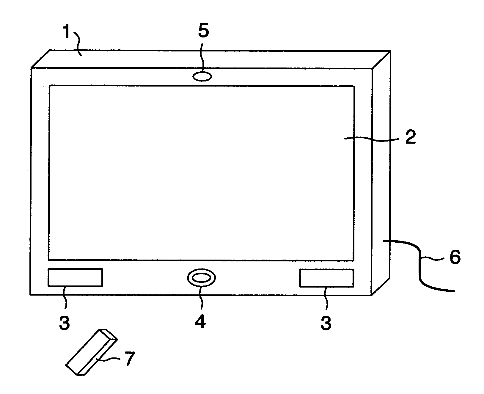
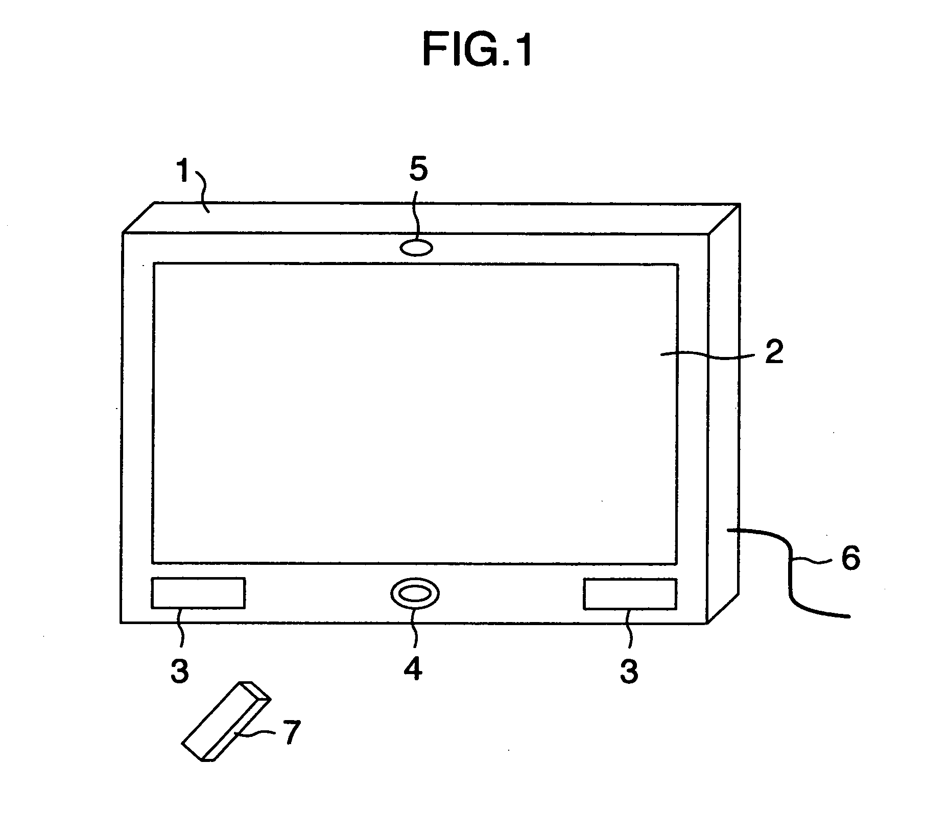
[0038]FIG. 1 is a diagram showing a perspective view of exterior appearance of a television (TV) receiver set with additional video telephone functionality in accordance with a The videophone function-added TV receiver is designated by reference numeral 1, which has a display screen 2, loudspeaker module 3, video camera 4, microphone 5, communications network cable 6, and wireless remote control device 7.

[0039]As shown in FIG. 1, the loudspeaker module 3 includes a couple of spaced-apart speakers, which are mounted in a front panel of housing of the videophone function-added TV receiver 1 at right and left side corners below the display screen 2. The camera 4 is embedded in the front panel at a center position of lower side which is midway between the right and left speakers. This camera 4 has its image pickup lens which is exposed to outside. The microphone 5 is built in the front panel of housing at an upper center position above the display screen 2. This first embodiment is the...

second embodiment

[0124]FIG. 8 is a diagram showing a perspective view of exterior appearance of a TV receiver set with additional videophone functions in accordance with a second embodiment, wherein reference numeral la designates an apparatus main body, numeral 30 denotes a video camera, and 31 indicates a connection cable. Constituent elements corresponding to those shown in FIG. 1 are indicated by the same reference numerals, and a detailed explanation thereof is eliminated herein.

[0125]The second embodiment shown in FIG. 8 is arranged so that the video camera 30 is detachably connected by the connection cable 31 to the apparatus main body 1a of videophone function-added TV receiver 1. This video camera 30 is independently usable when disconnected from the apparatus main body 1a of videophone function-added TV receiver 1 and is also usable as a videophone equipment together with the apparatus main body 1a when linked by the connection cable 31 to the apparatus main body 1a of videophone function-...

third embodiment

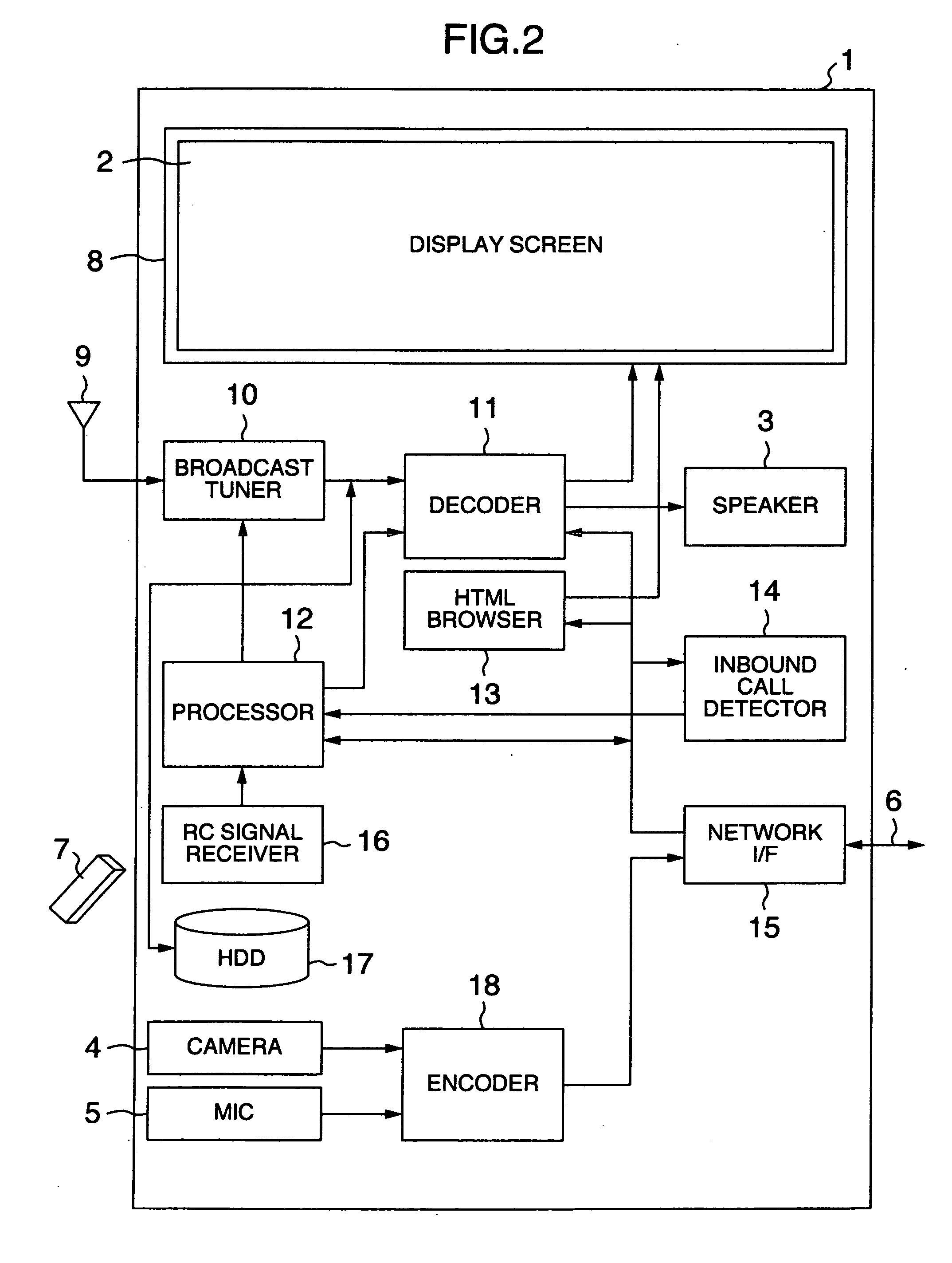
[0159]FIG. 12 is a block diagram showing a circuit configuration of a videophone function-added TV receiver set in accordance with a third embodiment, which includes a decoder 38 and an echo canceller 39. Components corresponding to those shown in FIG. 1 are denoted by the same reference numerals, and detailed explanations thereof are eliminated herein.

[0160]This third embodiment of FIG. 12 is different from the videophone function-added TV receiver 1 of the first embodiment shown in FIG. 2 in that the decoder 11 has only the TV program-use decode function and thus is for exclusive use in the TV broadcast program viewing function mode and in that the decoder 38 is additionally provided, which is for use in the videophone function mode and VOD function mode. This decoder 38 is connected to the network I / F 15. Also provided is the echo canceller 39 which removes or “cancels” an audio signal of a digital broadcast program signal of speakers 3 from an audio signal as output from microph...


PUM


Abstract

A videophone system includes a processor which selectively sets a television (TV) broadcast program viewing function mode and videophone function mode in response to manual operation of a remote control, a decoder which performs, in the TV program view mode, a TV program-use decode function for decoding a broadcast program signal received from a TV tuner to thereby display it on a display screen while producing audio sounds by loudspeakers and which performs, in the videophone function mode a videophone-use decode function for decoding a videophone signal received from a distant party to thereby display on the screen an image of the distant party using the screen and speakers, and an encoder which performs a videophone-use encode function for encoding a video signal from a camera and a voice signal from a microphone to generate a videophone signal, which is sent to the distant party via a network.

Description

INCORPORATION BY REFERENCE[0001]The present application claims priority from Japanese application JP2008-246232 filed on Sep. 25, 2008, the content of which is hereby incorporated by reference into this application.BACKGROUND OF THE INVENTION[0002]1. Field of the Invention[0003]The present technology relates to a television (TV) receiver set with TV phone functionality added thereto, which is arranged to have a video telephone call enabling means to thereby make it possible to perform video / voice-based telecommunication with another machine. This technology also relates to a TV phone system using videophone function-added TV receivers of this type.[0004]2. Description of the Related Art[0005]A telephone communication system and TV broadcast system are independently established systems. Traditionally, a telephone equipment and TV receiver set are quite different apparatuses. In cases where a telephone receives an incoming call and generates a ring sound or melody (calling sound) sign...

Claims


Application Information

Patent Timeline
Patent Type & Authority Applications(United States)
IPC IPC(8): H04N7/14H04N5/44
CPCH04N7/142H04N7/17318H04N21/254H04N7/141H04N21/4223H04N21/431H04N21/4788H04N21/42203H04N7/148H04N7/147H04L65/1063
Inventor IWABUCHI, KAZUNORIMIZOSOE, HIROKISHIMODA, MUTSUMIBONDAN, SETIAWANSASAMOTO, MANABU
Owner MAXELL HLDG LTD
Why Eureka
Try Eureka