Pulse wave measurement electrode unit and pulse wave measurement device

a technology of pulse wave and electrode, which is applied in the field of pulse wave measurement electrode unit and pulse wave measurement device, can solve the problems of high precision pulse wave measurement and measurement accuracy still not improving, and achieve the effect of high precision

Inactive Publication Date: 2010-03-25
OMRON HEALTHCARE CO LTD
View PDF5 Cites 95 Cited by
  • Summary
  • Abstract
  • Description
  • Claims
  • Application Information

AI Technical Summary

Benefits of technology

[0026]The pulse wave measurement device according to all aspects of the present invention may further include a compression mechanism for pressing a body surface of a living body to compress the artery; a compression force control unit for servo controlling a compression force on the artery by the compression mechanism based on information of the volume pulse wave obtained in the volume pulse wave acquiring unit; a compression force detection unit capable of detecting a co...

Problems solved by technology

However, when pulse wave measurement is performed using a pulse wave measurement electrode unit and a pulse wave measurement device equipped with the same having a configuration disclosed in Patent Document 1, a great amount of a body tissue portion other than an artery is included in a measuring site or a site where a constant current applied for pulse wave measurement passes, and an impedance fluctuation at the body tissue portion other than the artery superimposes the measure...

Method used


Image

  • Pulse wave measurement electrode unit and pulse wave measurement device
  • Pulse wave measurement electrode unit and pulse wave measurement device
  • Pulse wave measurement electrode unit and pulse wave measurement device

Examples


first embodiment

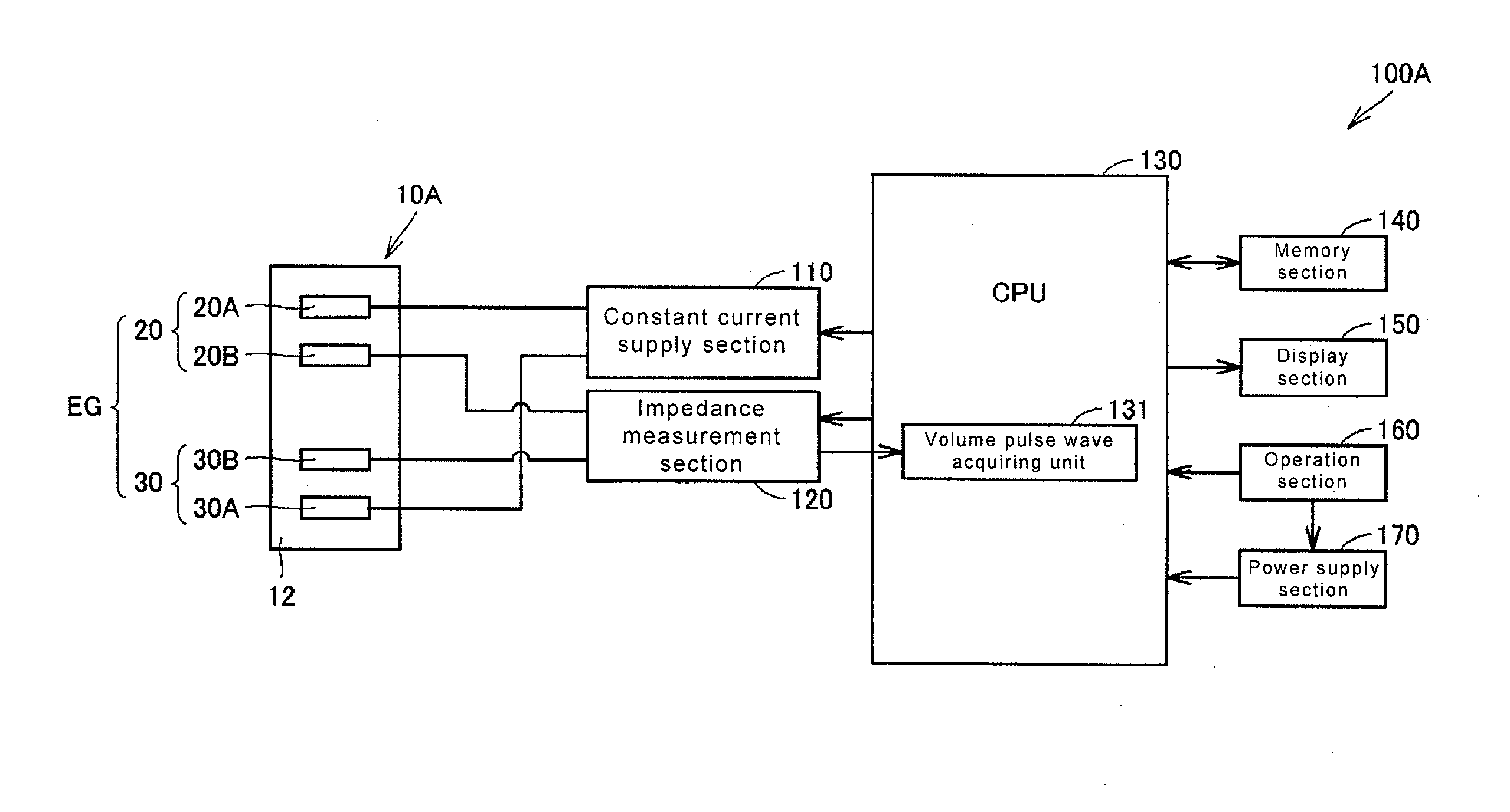
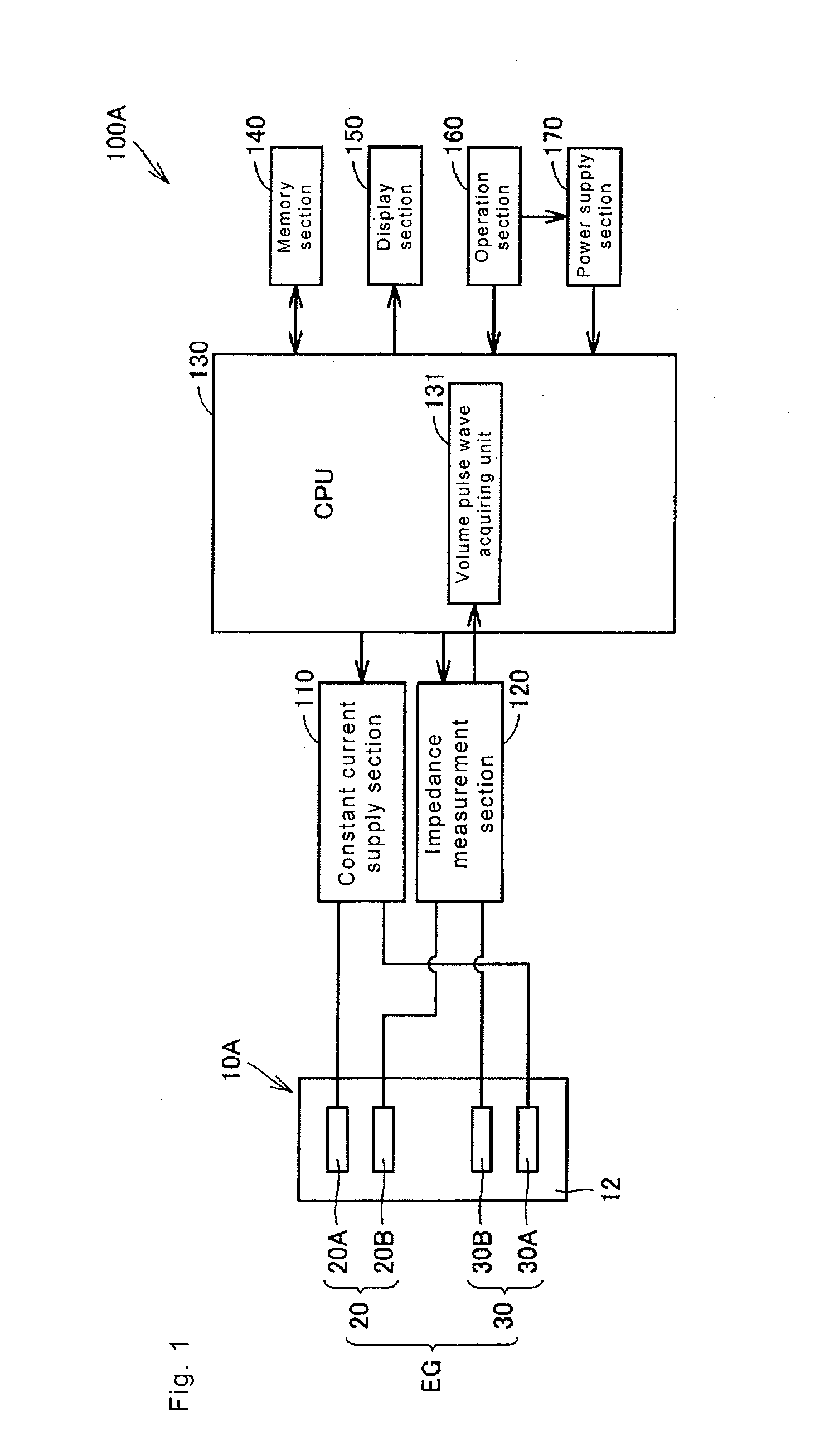
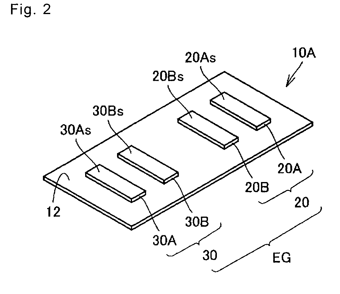
[0061]FIG. 1 is a function block diagram showing a configuration of a pulse wave measurement device according to a first embodiment of the present invention, and FIG. 2 is a schematic perspective view of a pulse wave measurement electrode unit according to the present embodiment. A configuration of a pulse wave measurement device 100A according to the present embodiment and an outer appearance structure of a pulse wave measurement electrode unit 10A will be described with reference to FIGS. 1 and 2.

[0062]As shown in FIG. 1, the pulse wave measurement device 100A according to the present embodiment mainly includes a pulse wave measurement electrode unit 10A, a constant current supply section 110, an impedance measurement section 120, a CPU 130, a memory section 140, a display section 150, an operation section 160, and a power supply section 170.

[0063]As shown in FIGS. 1 and 2, the pulse wave measurement electrode unit 10A is attached to a living body to measure a fluctuation of a bio...

second embodiment

[0092]FIG. 11 is a function block diagram showing a configuration of a pulse wave measurement device according to a second embodiment of the present invention, and FIG. 12 is a schematic perspective view of a cuff of the pulse wave measurement device according to the present embodiment. FIG. 13 is a cross-sectional view showing a state in which the cuff of the pulse wave measurement device according to the present embodiment is attached to the wrist. A configuration of a pulse wave measurement device 1008 according to the present embodiment and a structure of a cuff 180 will be described with reference to FIGS. 11 to 13. In the figure, the same reference symbols are denoted for the portions similar to the pulse wave measurement device 100A according to the first embodiment, and the description thereof will not be repeated.

[0093]As shown in FIGS. 11 to 13, the pulse wave measurement device 100B according to the present embodiment is equipped with a compression mechanism capable of li...

third embodiment

[0107]FIG. 16 is a function block diagram showing a configuration of a pulse wave measurement device according to a third embodiment of the present invention. A configuration of a pulse wave measurement device 100D according to the present embodiment will be described with reference to FIG. 16. In the figure, the same reference symbols are denoted for the portions similar to the pulse wave measurement device 100A according to the first embodiment, and the description thereof will not be repeated.

[0108]As shown in FIG. 16, the pulse wave measurement device 100D according to the present embodiment differs from the pulse wave measurement device 100A according to the first embodiment in the configuration of the pulse wave measurement electrode unit. In other words, in the pulse wave measurement electrode unit 10B of the pulse wave measurement device 100D according to the present embodiment, one of the pair of current application electrodes and one of the pair of voltage measurement elec...


PUM


Abstract

A pulse wave measurement electrode unit includes an electrode group and a supporting member. The electrode group includes a first electrode portion including a first current application electrode and a first voltage measurement electrode, and a second electrode portion, positioned spaced apart from the first electrode portion, including a second current application electrode and a second voltage measurement electrode. The supporting member supports the electrode group such that contacting surfaces of the electrodes with respect to a living body are arranged substantially on an identical plane. The electrodes are arranged lined in a direction an artery extends when the pulse wave measurement electrode unit is applied to the living body. According to such a configuration, a pulse wave measurement electrode unit having a simple configuration and enabling high precision volume pulse wave measurement can be provided.

Description

REFERENCE TO RELATED APPLICATIONS[0001]This application is a national stage application under 35 USC 371 of International Application No. PCT / JP2007 / 071910, filed Nov. 12, 2007, which claims the priority of Japanese Patent Application No. 2006-325914, filed Dec. 1, 2006, the contents of which prior applications are incorporated herein by reference.FIELD OF THE INVENTION[0002]The present invention relates to a pulse wave measurement electrode unit to be attached to a living body to acquire a volume pulse wave of an artery by measuring a fluctuation of a biological impedance, and a pulse wave measurement device equipped with the same.BACKGROUND OF THE INVENTION[0003]It is very important to measure a pulse wave of an artery of a subject in knowing a health condition of the subject. In recent years, measurement of the pulse wave of the artery of the subject is frequently being performed to understand a change and the like of a cardiac load and a hardness of the artery. A blood pressure ...

Claims


Application Information

Patent Timeline
IPC IPC(8): A61B5/024A61B5/296
CPCA61B5/021A61B5/0245A61B2562/046A61B5/6843A61B2562/0209A61B5/0535A61B2562/0215
Inventor MATSUMURA, NAOMISAWANOI, YUKIYAIWAHORI, TOSHIYUKI
Owner OMRON HEALTHCARE CO LTD
Why Eureka
Try Eureka